Joining process for superalloys

a superalloy and bonding technology, applied in the field of superalloy bonding methods, can solve the problems of low casting yield of large superalloy components, failure of mechanically sound joints of superalloys, and prior art focusing on joining processes, including welding and brazing

Active Publication Date: 2014-12-18
GENERAL ELECTRIC CO
View PDF11 Cites 2 Cited by
  • Summary
  • Abstract
  • Description
  • Claims
  • Application Information

AI Technical Summary

Benefits of technology

[0009]The present invention may address one or more of the problems and deficiencies of the art discussed above. However, it is contemplated that the invention may prove useful in addressing other proble...

Problems solved by technology

However, such large superalloy components typically suffer from low casting yield due to the size, complex shape, and/or presence of core.
Even for smaller components, casting a single component can be less than ideal due to, for example, complex shapes required of the component.
However, thus far, prior art focusing on joining processes, including welding and brazing, for superalloys has failed to produce mechanically sound joints.
When super...

Method used


Image

  • Joining process for superalloys
  • Joining process for superalloys
  • Joining process for superalloys

Examples


example a

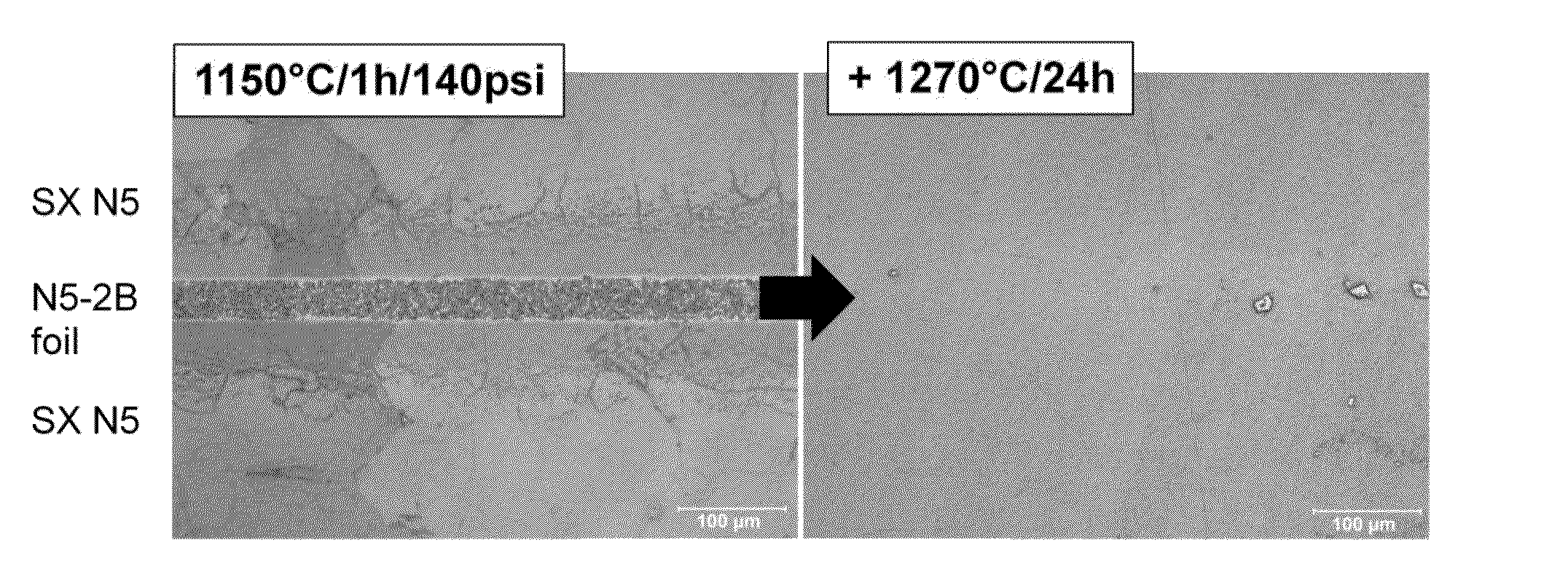
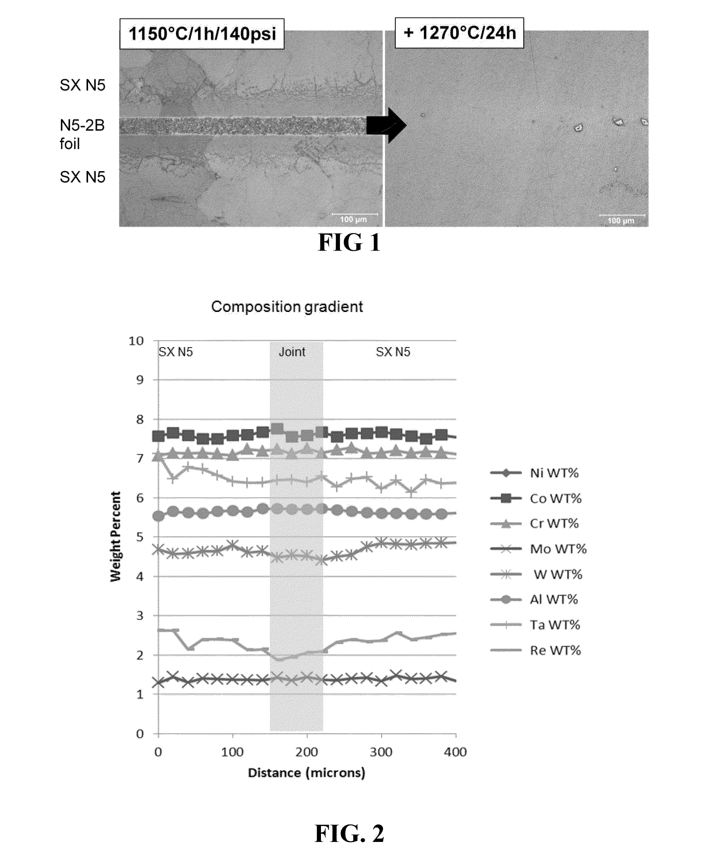
[0071]Two Rene N5 nickel-based single crystal superalloy subcomponents (composition shown in Table I) were prepared by finishing with low stress grinding, such that the subcomponents had less than 10° crystal orientation deviation from each other, had substantially flat mating surfaces, and were smooth and clean. The Rene N5 subcomponents were aligned with a ˜2 mil thick N5-2B foil (see Table I), which comprised 2 wt % boron, as filler material in a fixture, and pressure was applied at about 1 MPa. In vacuum environment, the aligned subcomponents were subjected to a first heat treatment while in the fixture at 1150° C. for one hour, then the subcomponents were allowed to cool to room temperature. During the first heat treatment, the filler partially melted, and the subcomponents were metallurgically joined. Following heating, the joint area was made up of fine grains.

[0072]The cooled joined components were removed from the fixture, and, in the absence of pressure, were subjected to ...

example b

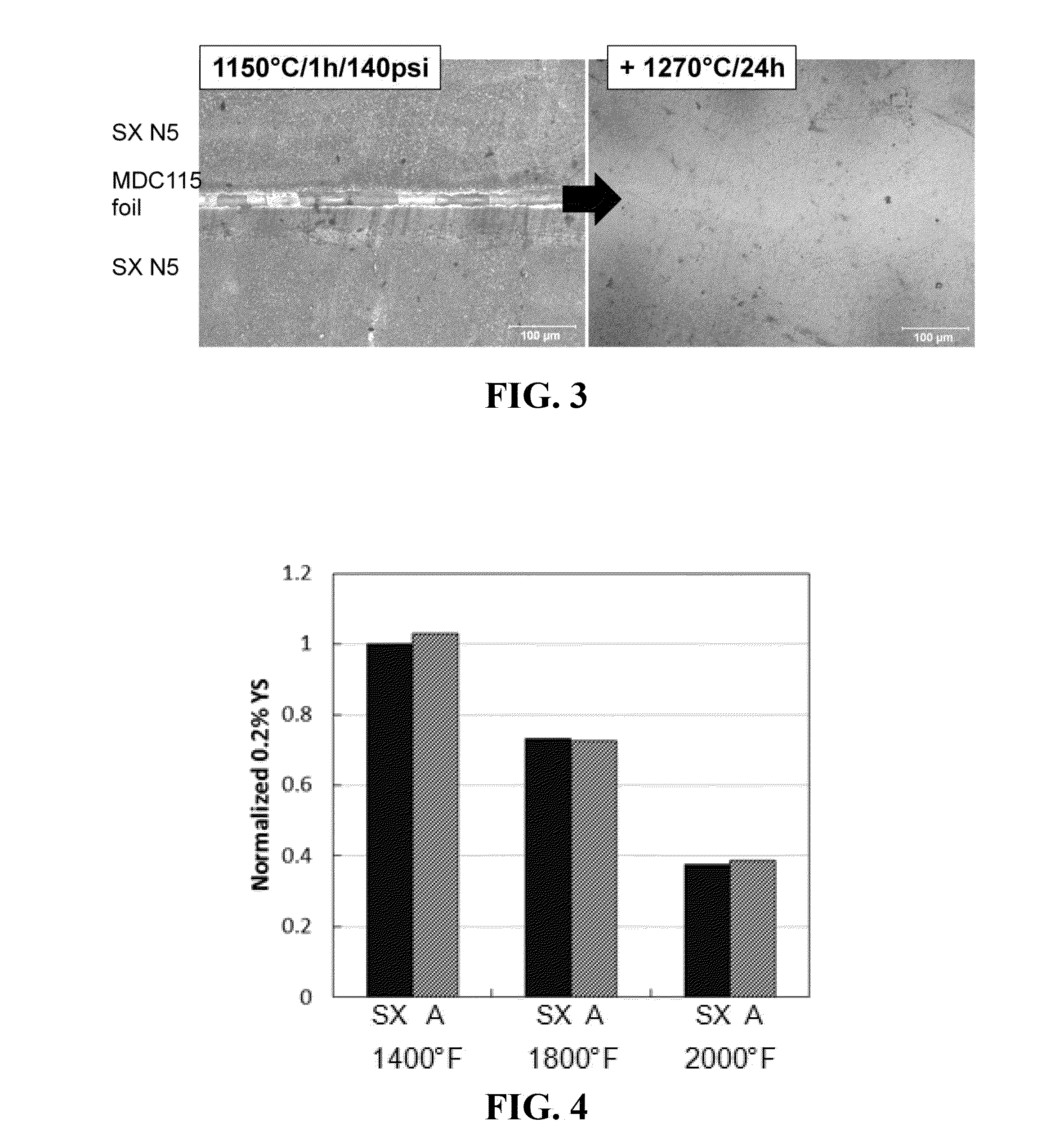
[0073]Example B was prepared following the protocol set forth above for Example A, except that for Example B, instead of using the N5-2B foil, the Rene N5 subcomponents were aligned in a fixture with a ˜2 mil thick MDC 115 foil (see Table I) comprising 3 wt % boron, obtained from Materials Development Corporation, as filler material. FIG. 3 is a photo micrograph showing the microstructure change at the joint following the first and second heat treatments.

Analysis of Inventive Example A

[0074]High temperature tensile and creep properties of the single-crystal Rene N5 subcomponents joined with the N5-2B foil comprising 2 wt % boron (Example A) were measured and compared with a single crystal Rene N5 superalloy without a joint (Counter Example SX). The joined N5 was solution treated at 1300° C. for 2 h, followed by aging treatments at 1120° C. / 4 h, 1080° C. / 4 h and 900° C. / 4 h. FIG. 4 depicts a chart showing the results of the normalized yield strength testing. FIG. 5 depicts a chart sh...


PUM

PropertyMeasurementUnit
Timeaaaaaaaaaa
Thicknessaaaaaaaaaa
Pressureaaaaaaaaaa

Abstract

A method of bonding superalloys is provided. The method includes: aligning a first superalloy subcomponent having a gamma-prime solvus g′1 and a second superalloy subcomponent having a gamma-prime solvus g′2, with a filler material that includes at least 1.5 wt % boron disposed between the first and second superalloy subcomponents; performing a first heat treatment at a temperature T1, where T1 is above the solidus of the filler material and below the liquidus of the filler material; and performing a second heat treatment at a temperature T2, where T2 is greater than T1, and where T2 is greater than or equal to the lower of g′1 and g′2.

Description

BACKGROUND[0001]The invention includes embodiments that relate to a method of bonding superalloys. More particularly, the invention relates to a semi-solid method of bonding superalloys.[0002]Superalloy components are commonly used in various applications, including, for example, in aircraft engine, gas turbine, and marine turbine industries. Generally, the quality of the superalloy components is imperative to their successful function. To achieve the requisite quality products, even very large superalloy components (e.g., first stage buckets of gas turbines) are often cast so as to avoid joining (bonding) components wherever possible. However, such large superalloy components typically suffer from low casting yield due to the size, complex shape, and / or presence of core. Even for smaller components, casting a single component can be less than ideal due to, for example, complex shapes required of the component.[0003]Segmenting superalloy components into smaller multiple subcomponent...

Claims


Application Information

Patent Timeline
IPC IPC(8): B23K20/22
CPCB23K20/22B23K35/3033B23K35/304B23K35/0233C22C19/057C22F1/10
Inventor SUZUKI, AKANESCHOONOVER, JEFFREY JONWARK, DAVID AUSTIN
Owner GENERAL ELECTRIC CO
Why Eureka
Try Eureka