Al technical title is built by PatSnap Al team. It summarizes the technical point description of the patent document.
A technology for a water drilling rig and a processing head, which is applied to metal processing equipment, machine tools suitable for grinding workpiece edges, and manufacturing tools, etc., can solve the problems of complex process, time-consuming and laborious, and high cost, achieve a sophisticated layout structure, and reduce production costs. , the effect of low manufacturing cost
Inactive Publication Date: 2009-06-24
黄祖伟
View PDF7 Cites 0 Cited by
Summary
Abstract
Description
Claims
Application Information
AI Technical Summary
This helps you quickly interpret patents by identifying the three key elements:
Problems solved by technology
Method used
Benefits of technology
Problems solved by technology
[0004] One of the technical problems to be solved by the present invention is to overcome the problem that it is difficult to process more than 8 faces of small rhinestones in the prior art, thereby affecting or limiting the processing effect and precision, and to provide a rhinestone facet as any facet The second technical problem to be solved by the present invention is to overcome the problems of complicated process, time-consuming, laborious, high cost and much waste existing in the prior art, and provide a kind of integrated grinding processing head. Integrated with polishing, it can automatically adjust the height of the throwing disc or grinding disc, and can control the facet of the rhinestone at any angle. It is a water drilling machine with simple operation, accurate and fine control, and low manufacturing cost.
Method used
Image
Click on the blue label to locate the original text in one second.
Reading with bidirectional positioning of images and text.
Examples
Embodiment Construction
[0019] Below by embodiment and with reference to accompanying drawing, the present invention will be further described.
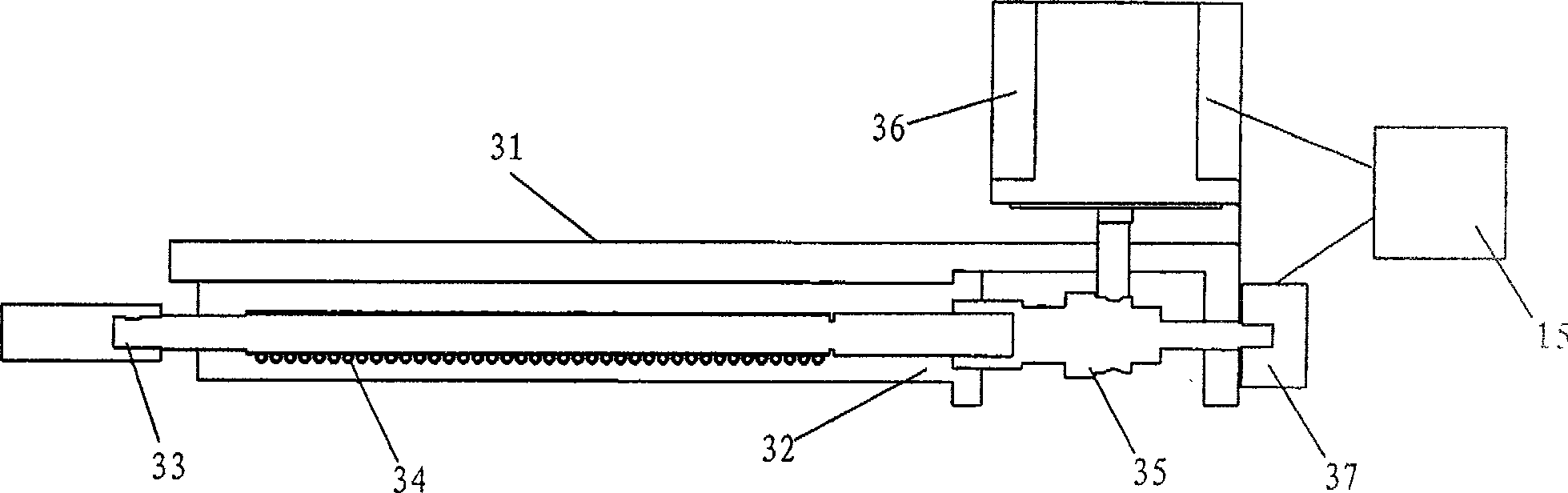
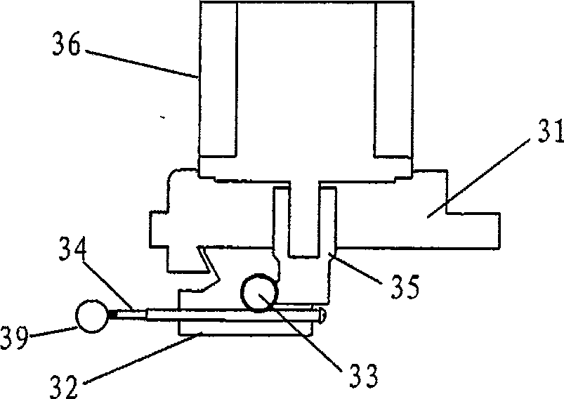
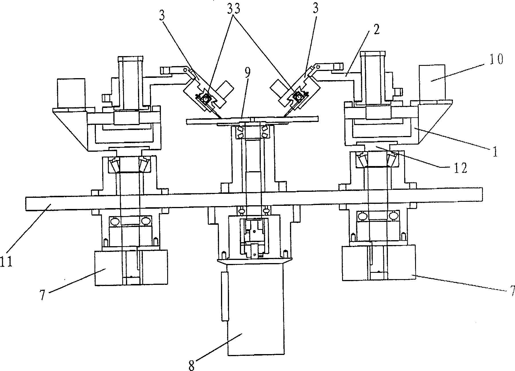
[0020] see figure 1 , figure 2 In the embodiment of the present invention, the rhinestone processing head 3 is provided with a clamp mounting plate 31, a housing 32, a clamp shaft 33, a clamp needle 34, a shaft coupling 35, a processing head stepping motor 36, and a signal collector 37. The housing 32 is installed on On the clamp mounting plate 31, the clamp shaft 33 is sleeved on the coupling 35, the clamp shaft 33 is connected with the clamp pin 34 in a worm gear mode and installed in the housing 32, the clamp (including the housing 32, the clamp shaft 33, the clamp pin 34) It can be loaded and unloaded freely. The processing head stepper motor 36 is installed on the fixture mounting plate 31 and connected with the shaft coupling 35 , and the signal collector 37 is connected with the shaft coupling 35 and used for reading the rotation angle signal of t...
PUM
Abstract
The invention relates to a water drilling processing head and a water drilling machine, belonging to the field of jewelry processing. The rhinestone processing head includes a fixture mounting plate, a fixture, a coupling, a processing head stepping motor, and a signal collector. The fixture is installed on the fixture mounting plate, the fixture is connected to the coupling, and the stepping motor of the processing head is connected to the coupling. , the signal collector is connected with the coupling, and the processor is connected with the signal collector and the stepping motor of the processing head. The water drilling machine is provided with a platen, a frame, a machine head, a water drilling processing head, a swing motor, a grinding disc, a throwing disc, a height adjuster, a grinding disc motor, a disc throwing motor, a rotating cylinder and a processor. On the regulator, the disc throwing motor is connected with the disc throwing, the swing motor is installed on the frame and connected with the machine head, the rotating cylinder is used to control the working position of the rhinestone processing head, the rhinestone processing head is connected with the machine head, and the machine head is connected with the frame. The invention realizes the automatic determination and adjustment of the facets of the rhinestones in the process of the rhinestones processing through the numerical control method, and has the advantages of simple operation, accurate and fine control, low manufacturing cost and the like.
Description
Technical field: [0001] The invention relates to a rhinestone processing device, in particular to a rhinestone processing head and a water drilling machine with the rhinestone processing head, belonging to the field of jewelry processing. Background technique: [0002] The existing domestic rhinestone processing equipment generally uses mechanical devices to control the facet angle of the rhinestone, and can only perform a single fixed indexing, that is, the same set of rhinestone fixtures can only handle one facet angle; while the more advanced The equipment uses servo motors to control any angle of the rhinestone facets, but the manufacturing cost is relatively expensive. In traditional rhinestone production, for the processing of rhinestones with different diameters, the fixture shaft is generally made into a worm screw with a modulus corresponding to the diameter of the rhinestone, and the fixture needle is made into a worm gear with a modulus corresponding to the diamet...
Claims
Application Information
Patent Timeline
Application Date:The date an application was filed.
Publication Date:The date a patent or application was officially published.
First Publication Date:The earliest publication date of a patent with the same application number.
Issue Date:Publication date of the patent grant document.
PCT Entry Date:The Entry date of PCT National Phase.
Estimated Expiry Date:The statutory expiry date of a patent right according to the Patent Law, and it is the longest term of protection that the patent right can achieve without the termination of the patent right due to other reasons(Term extension factor has been taken into account ).
Invalid Date:Actual expiry date is based on effective date or publication date of legal transaction data of invalid patent.