Method for reducing friction between piston and cylinder wall of internal-combustion engine, and Oil saving piston
What is Al technical title?
Al technical title is built by PatSnap Al team. It summarizes the technical point description of the patent document.
A technology of internal combustion engine cylinders and pistons, applied in the directions of pistons, mechanical equipment, engine components, etc., can solve the problems of reducing the amount of lubricating oil, increasing the gap between the piston and the cylinder, increasing the vibration and noise of the engine, and achieving increased power output, The effect of reducing fuel consumption and reducing friction
Inactive Publication Date: 2009-07-22
王德恒 +1
View PDF8 Cites 4 Cited by
Summary
Abstract
Description
Claims
Application Information
AI Technical Summary
This helps you quickly interpret patents by identifying the three key elements:
Problems solved by technology
Method used
Benefits of technology
Problems solved by technology
The disadvantage is that part of the peripheral surface of the above-mentioned piston is close to the inner surface of the cylinder. As the closest position is moved along the circumferential direction, the gap between the piston and the cylinder becomes larger, and the oil held in the groove of the piston skirt is pushed to both sides of the groove. , reducing the amount of lubricating oil held in the groove
The disadvantage is that the area of the piston skirt is small, which cannot guarantee the stability of the piston movement and increases the vibration and noise of the engine.
Its disadvantage is that the lubricating oil cannot reach the piston skirt quickly, but splashes to the cylinder wall through the high-speed operation of the engine.
When the piston descends, the sharp edge of the lower edge of the piston skirt will remove most of the lubricating oil existing on the cylinder wall, resulting in a decrease in the oil film area between the piston skirt and the cylinder wall, resulting in poor lubrication
So, there is room for improvement
Method used
Image
Click on the blue label to locate the original text in one second.
Reading with bidirectional positioning of images and text.
Examples
Embodiment Construction
[0025] Below in conjunction with accompanying drawing and specific embodiment the present invention is described in further detail:
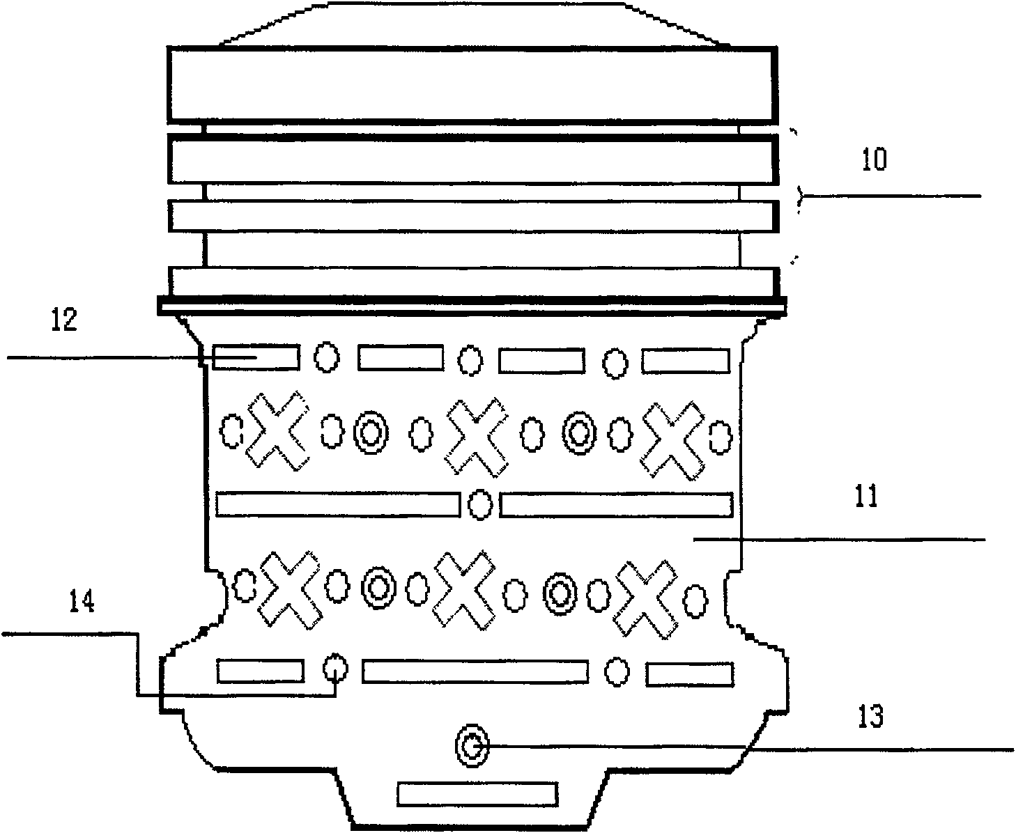
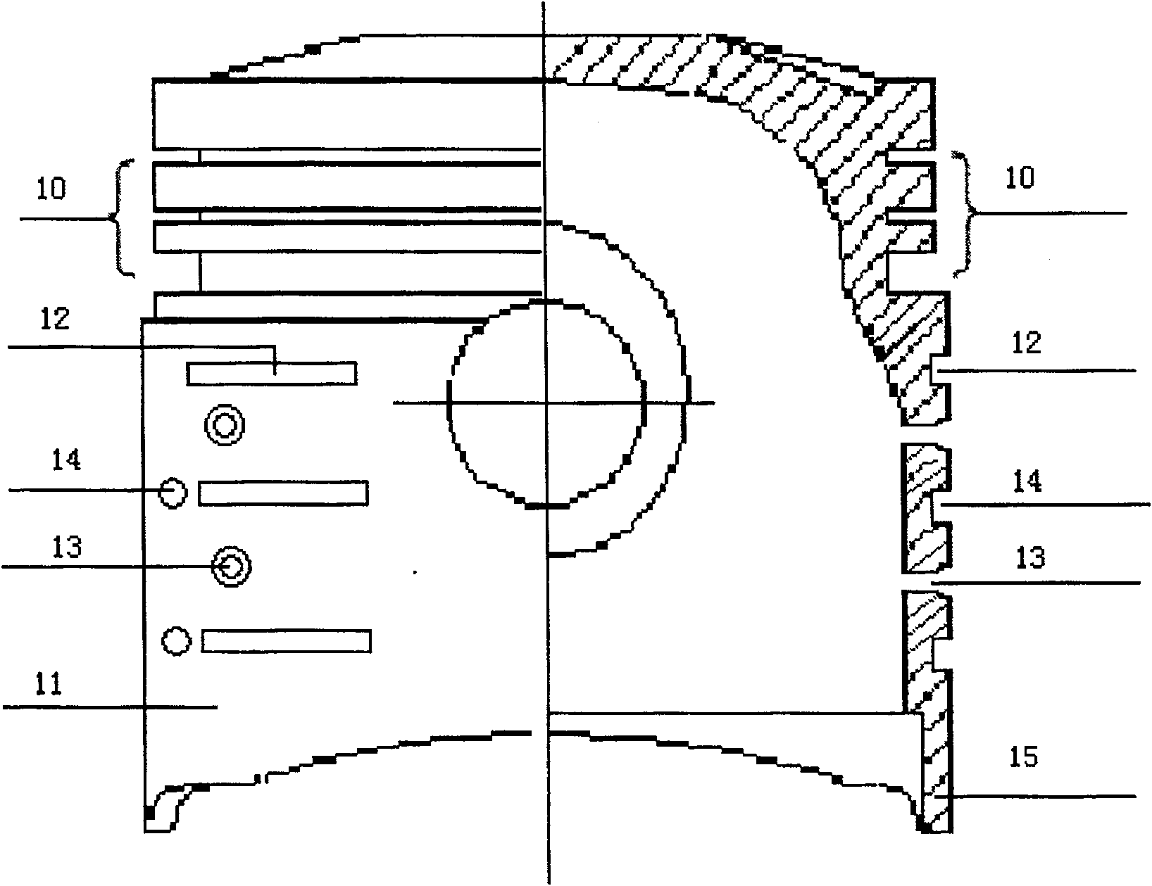
[0026] figure 1 , 2 Shown is the front view and cross-sectional view of the pistons of Embodiments 1 and 2 of the present invention.
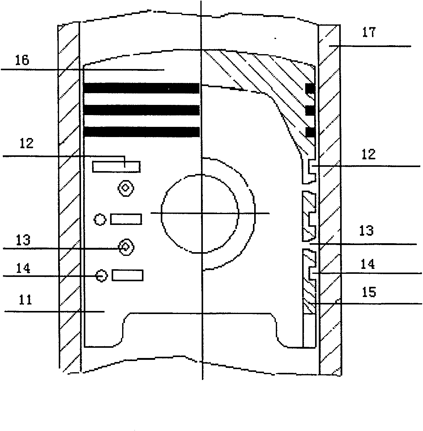
[0027] image 3 The illustrated embodiment 1 and 2 of the present invention. When the internal combustion engine is working, the piston 16 reciprocates at a high speed in the cylinder wall 17, continuously guides the lubricating oil through the through hole 13 of the piston skirt and quickly flows into the surface of the piston skirt 11, and stores the lubricating oil in the recess provided on the piston skirt. Groove 12 and the non-through hole 14 that this piston skirt portion is provided with, so that between this internal combustion engine cylinder wall 17 and this piston skirt portion 11 surface, distribute enough lubricating oil all the time, and isolated internal combustion engine cylinder wall 17 and p...
PUM
Abstract
The invention provides a method for reducing the friction between the piston and the cylinder wall of an internal combustion engine, comprising the following steps: (a) constantly guiding the lubricating oil to flow to the surface of the piston skirt through the through hole provided on the piston skirt during the movement of the piston and (b) storing lubricating oil in the groove provided on the piston skirt and the non-through hole of the piston skirt, so that a sufficient amount of lubricating oil is always applied between the cylinder wall of the internal combustion engine and the surface of the piston skirt lubricating oil, and isolate the metal contact between the cylinder wall and the piston skirt, and finally reduce the friction between the piston skirt and the cylinder wall, reduce the internal combustion engine friction work loss, heat power consumption, and improve the internal combustion engine Higher power output, lower fuel consumption, noise and emissions. To achieve the dual benefits of fuel saving and environmental protection. In order to achieve the purpose of the method and steps for reducing the friction between the piston and the cylinder wall of the internal combustion engine, the invention provides a fuel-saving piston of the internal combustion engine, the piston comprising: a piston skirt, a piston skirt wall, and a piston ring. A plurality of grooves are formed in the piston skirt, a plurality of through holes are formed in the piston skirt, and a plurality of non-through holes are formed in the piston skirt. The piston skirt groove provides storage lubricating oil, the piston skirt through hole provides supply lubricating oil, and the piston skirt non-through hole provides storage lubricating oil. The present invention can be widely applied to: internal combustion engines, including vehicles, ships, tanks, generators, mining machinery, compressors and the like. The fuel saving effect and environmental protection benefit are very remarkable.
Description
Technical field: [0001] The invention relates to a piston of an internal combustion engine. In particular, it relates to a method and a step for reducing the friction between a piston and a cylinder wall of an internal combustion engine and a fuel-saving piston of an internal combustion engine for realizing the method and the step. Background technique [0002] The piston is the "heart" of the internal combustion engine, which bears alternating mechanical loads and thermal loads, and is one of the key components with the worst working conditions in the internal combustion engine. The function of the piston is to withstand the gas pressure and transmit it to the connecting rod through the piston pin to drive the crankshaft to rotate. The piston works under the conditions of high temperature, high pressure and high speed. Therefore, it is severely heated, and due to the inherent characteristics of the structure, the heat dissipation conditions are poor. When the piston works ...
Claims
Application Information
Patent Timeline
Application Date:The date an application was filed.
Publication Date:The date a patent or application was officially published.
First Publication Date:The earliest publication date of a patent with the same application number.
Issue Date:Publication date of the patent grant document.
PCT Entry Date:The Entry date of PCT National Phase.
Estimated Expiry Date:The statutory expiry date of a patent right according to the Patent Law, and it is the longest term of protection that the patent right can achieve without the termination of the patent right due to other reasons(Term extension factor has been taken into account ).
Invalid Date:Actual expiry date is based on effective date or publication date of legal transaction data of invalid patent.