
Anaerobic reactor

An anaerobic reactor and reactor technology, applied in the field of water treatment, can solve the problems of substandard water outlet effect, high manufacturing and maintenance costs, complex reactor structure, etc., and achieve reduced equipment materials and maintenance costs, high removal rate , Enhance the effect of hydraulic turbulence intensity

Active Publication Date: 2009-08-05
TONGJI UNIV
View PDF2 Cites 0 Cited by
  • Summary
  • Abstract
  • Description
  • Claims
  • Application Information

AI Technical Summary

Problems solved by technology

[0005] For example, EGSB maintains a very high water flow rate in the entire reactor, and due to the cohesion of the methane bubbles generated, the water flow rate at the three-phase separator is quite high. When the operating conditions change greatly, a large amount of The loss of biological organisms, resulting in the substandard water discharge effect of the system, and in severe cases, the system collapses
In some established projects in European and American countries, due to the instability of the system, the rising flow rate has to be kept in a low range during operation, which reduces the processing capacity; and the structure of the IC reactor is actually the structure of two UASB reactors. Superposition, using the generated air bubbles to drive the granular sludge to circulate in the reaction zone. Since the reactor has two three-phase separators, the structure of the reactor is complicated, and the manufacturing and maintenance costs are high; at the same time, the start-up time is long and the technical requirements are high. As a developing country, only a small number of large companies can afford its construction and maintenance costs

Method used


Image

  • Anaerobic reactor
  • Anaerobic reactor
  • Anaerobic reactor

Examples


Embodiment Construction

[0026] The present invention will be further described below in conjunction with the accompanying drawings and the implementation process.

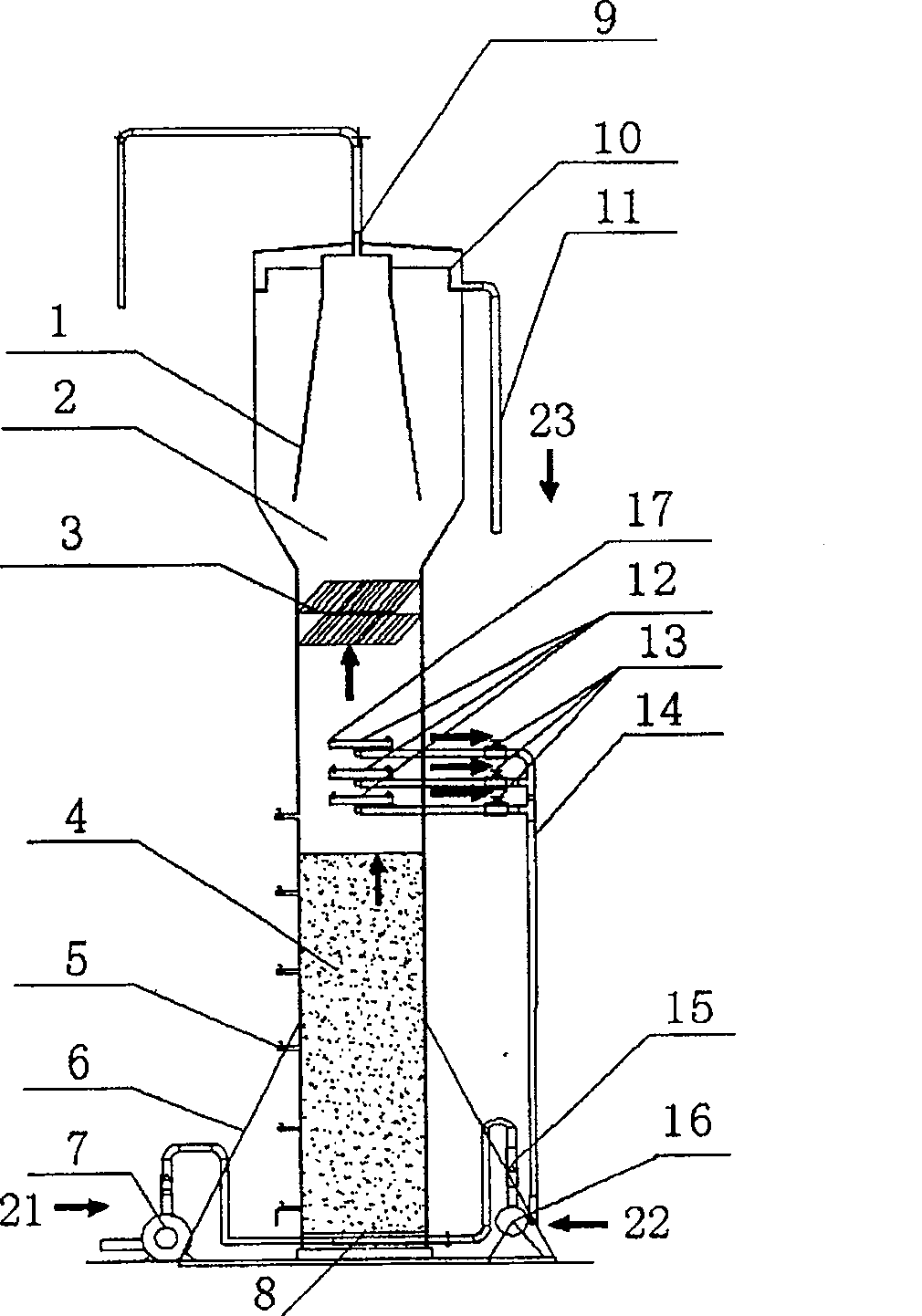
[0027] An anaerobic high-efficiency reactor, which mainly includes: a shell, a supporting base 19, a water distributor 8, a water distributor 12, an inclined plate settler 3, a three-phase separator 1, a mud discharge port 5, a water inlet pump 7, Circulation pump 16, flow meter 15, overflow tank 10, etc.

[0028] A set of water distributor 12 and corresponding control valve 13 are installed between the upper end of the sludge expansion zone 4 and the inclined plate settler 3 (see figure 2 ). One end of the water distributor 8 is connected to the water inlet pump 7, and the other end is connected to the circulation pump 16 (see image 3 ). There is a row of mud outlets 5 along different heights on the reactor shell (see figure 1 ); Between the water distributor 8 and the three-phase separator 1, an inclined plate settler 3 is install...


PUM

PropertyMeasurementUnit
angleaaaaaaaaaa

Abstract

An anaerobic reactor for treating sewage is divided into upper three-phase separation region and lower sludge expanding region, and is composed of base, cylindrical casing on base, water distributor connected between water inlet pump and circulating pump, three-phase separator, slant depositor, and control valves.

Description

technical field [0001] The invention belongs to the field of water treatment and relates to an anaerobic reaction device in the water treatment industry. Background technique [0002] At present, the sewage treatment rate in cities and towns in my country is very low, and most domestic and production wastewater are directly discharged into rivers without treatment, resulting in serious water pollution. The advanced urban sewage treatment technology shows that although the pollutant removal rate is high, it has the disadvantages of large area, high basic investment and high operating costs, which makes it difficult for many sewage treatment plants to raise funds to build or maintain operation due to high costs. Anaerobic treatment technology has become an energy-saving technology that is widely concerned at home and abroad because it does not require aeration, produces less sludge, and can recover biogas. [0003] In the development of anaerobic biological treatment process, ...

Claims


Application Information

Patent Timeline
Patent Type & Authority Patents(China)
IPC IPC(8): C02F3/28
Inventor 张亚雷赵建夫张选军蒋柱武周雪飞
Owner TONGJI UNIV
Learn More