
Printed circuit board with improved differential via

A printed circuit board and differential via technology, which is applied in printed circuit, printed circuit, printed circuit manufacturing, etc., can solve the problems of increasing manufacturing cost and improving the difficulty of manufacturing process, and achieve the effect of improving transmission characteristics

Inactive Publication Date: 2009-08-19
HONG FU JIN PRECISION IND (SHENZHEN) CO LTD +1
View PDF4 Cites 2 Cited by
  • Summary
  • Abstract
  • Description
  • Claims
  • Application Information

AI Technical Summary

Problems solved by technology

Although it is possible to reduce the spacing of differential vias to achieve a symmetrical effect as much as possible, this will increase the difficulty of the manufacturing process and increase the manufacturing cost.

Method used


Image

  • Printed circuit board with improved differential via
  • Printed circuit board with improved differential via
  • Printed circuit board with improved differential via

Examples


Embodiment Construction

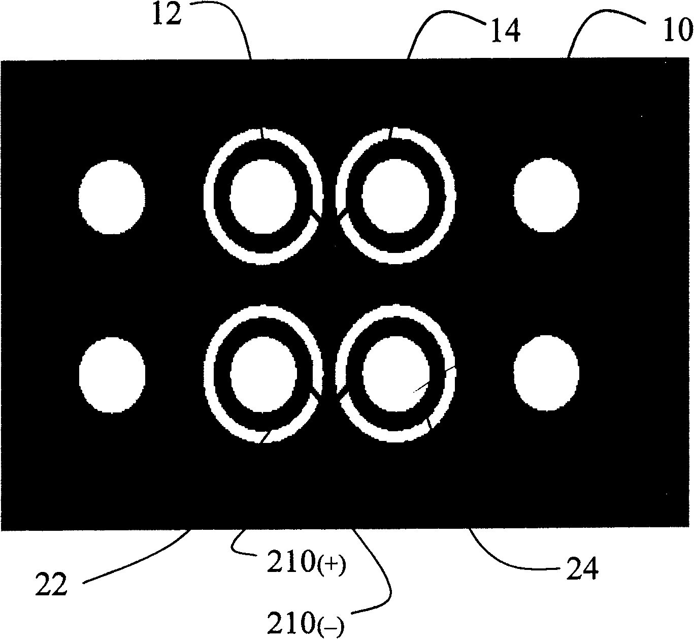
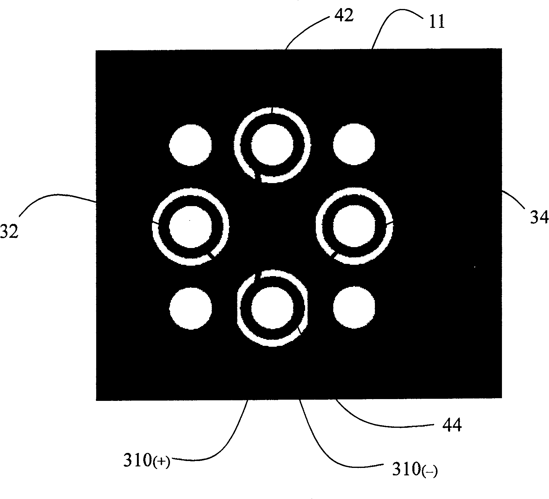
[0015] In the printed circuit board with improved differential vias in the preferred embodiment of the present invention, several groups of differential vias are provided on the PCB. Since the distance between the groups is relatively long, the crosstalk between them can be ignored, so only Consider crosstalk between differential vias of the same group. figure 2 Only one set of differential vias is shown, the set of differential vias includes a first pair of differential vias and a second pair of differential vias, the first pair of differential vias includes vias 32 and vias 34 , the second pair of differential vias includes vias 42 and vias 44 , and the two vias included in each pair of differential vias are of the same type, and the types include blind vias, buried vias and through vias. The first pair of differential vias in this design is located on the perpendicular bisector of the line connecting the centerlines of the second pair of differential vias, and the second p...


PUM


Abstract

The present invention provides a printed circuit board with improved differential vias. The printed circuit board includes several groups of differential vias and differential transmission lines corresponding to the above-mentioned differential vias, and several planes whose electrical connection is ensured by the above-mentioned differential transmission lines. Each group of differential vias includes two pairs of differential vias, wherein one pair of differential vias in the group of differential vias is on the perpendicular bisector of the line connecting the centerlines of the other pair of differential vias. Through the above design, the crosstalk between the differential vias on the printed circuit board cancels each other out, thereby improving the quality of signal transmission.

Description

【Technical field】 [0001] The present invention relates to a printed circuit board (Printed Circuit Board, hereinafter referred to as PCB), in particular to a printed circuit board with improved differential vias to improve signal transmission characteristics. 【Background technique】 [0002] With the improvement of the output switching speed of integrated circuits and the increase of the wiring density of printed circuit boards, the improvement of signal transmission characteristics has become one of the issues that designers of high-speed digital printed circuit boards must pay attention to. [0003] In the field of digital circuit design, crosstalk between signal lines exists widely, and crosstalk is the electromagnetic coupling between two signal lines. Mutual inductance and mutual capacitance between signal lines will cause noise on the line, in which capacitive coupling is externally expressed as coupling current, inductive coupling is externally expressed as coupling vo...

Claims


Application Information

Patent Timeline
Patent Type & Authority Patents(China)
IPC IPC(8): H05K1/02H05K3/00H04B3/32
CPCH05K1/0245Y10T29/49155H05K2201/09236H05K1/0216H05K1/115H05K1/0251
Inventor 林有旭叶尚苍李传兵
Owner HONG FU JIN PRECISION IND (SHENZHEN) CO LTD
Features
  • Generate Ideas
  • Intellectual Property
  • Life Sciences
  • Materials
  • Tech Scout
  • Unparalleled Data Quality
  • Higher Quality Content
  • 60% Fewer Hallucinations
Learn More