Absorption type refrigerator
An absorption refrigerator and absorber technology, applied in the direction of adsorption machines, refrigerators, refrigeration components, etc., can solve the problems that it is difficult to prevent low-temperature water from freezing, and achieve the effects of preventing freezing, inhibiting cooling, and inhibiting overcooling
- Summary
- Abstract
- Description
- Claims
- Application Information
AI Technical Summary
Problems solved by technology
Method used
Image
Examples
Embodiment 1
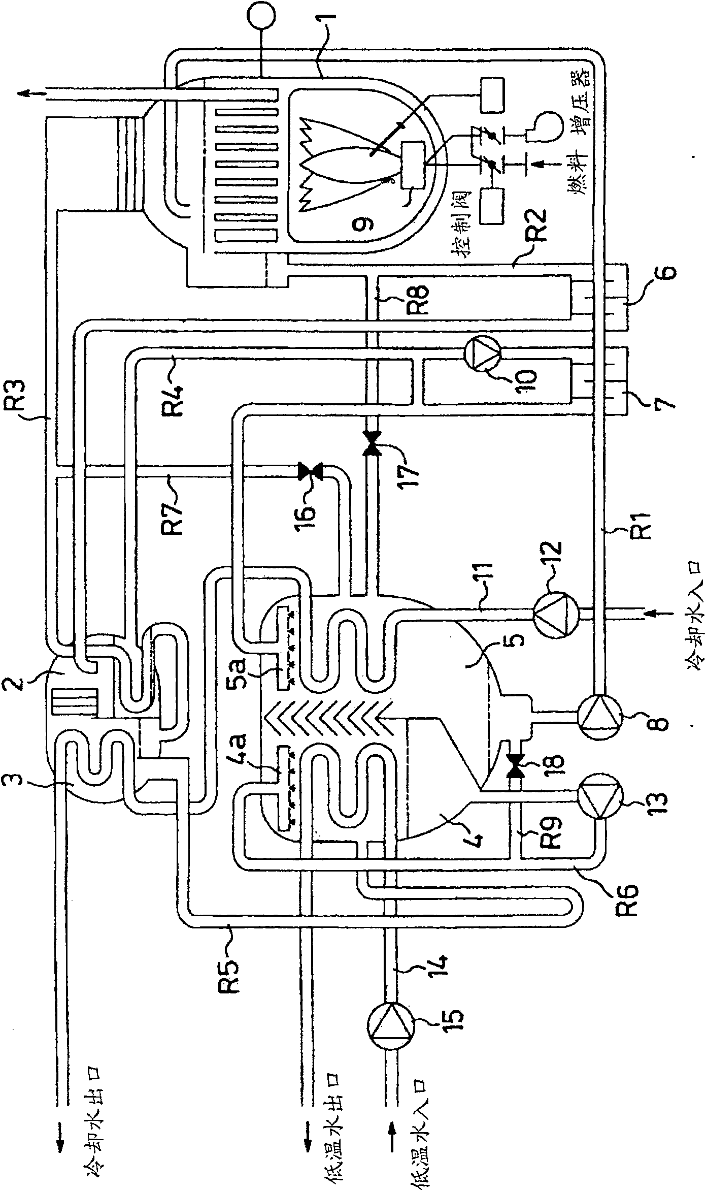
[0043] In the high-temperature regenerator 1, the dilute absorption liquid returned from the absorber 5 through the pipeline R1 by the dilute absorption liquid pump 8 is accommodated. . In this way, the dilute absorption liquid becomes a medium-concentrated absorption liquid, which is supplied to the low-temperature regenerator 2 through the pipeline R2, and passes through the high-temperature heat exchanger 6 halfway through heat exchange with the dilute absorption liquid flowing through the pipeline R1. The heat is dissipated and stored in the low-temperature regenerator 2 . On the other hand, the evaporated refrigerant vapor is supplied to the condenser 3 through the pipeline R3, and when passing through the low-temperature regenerator 2, it dissipates heat by exchanging heat with the medium-concentrated absorption liquid contained in the low-temperature regenerator 2 , becomes a vapor-liquid mixture, and then condenses to become a refrigerant liquid, which is stored at th...
Embodiment 2
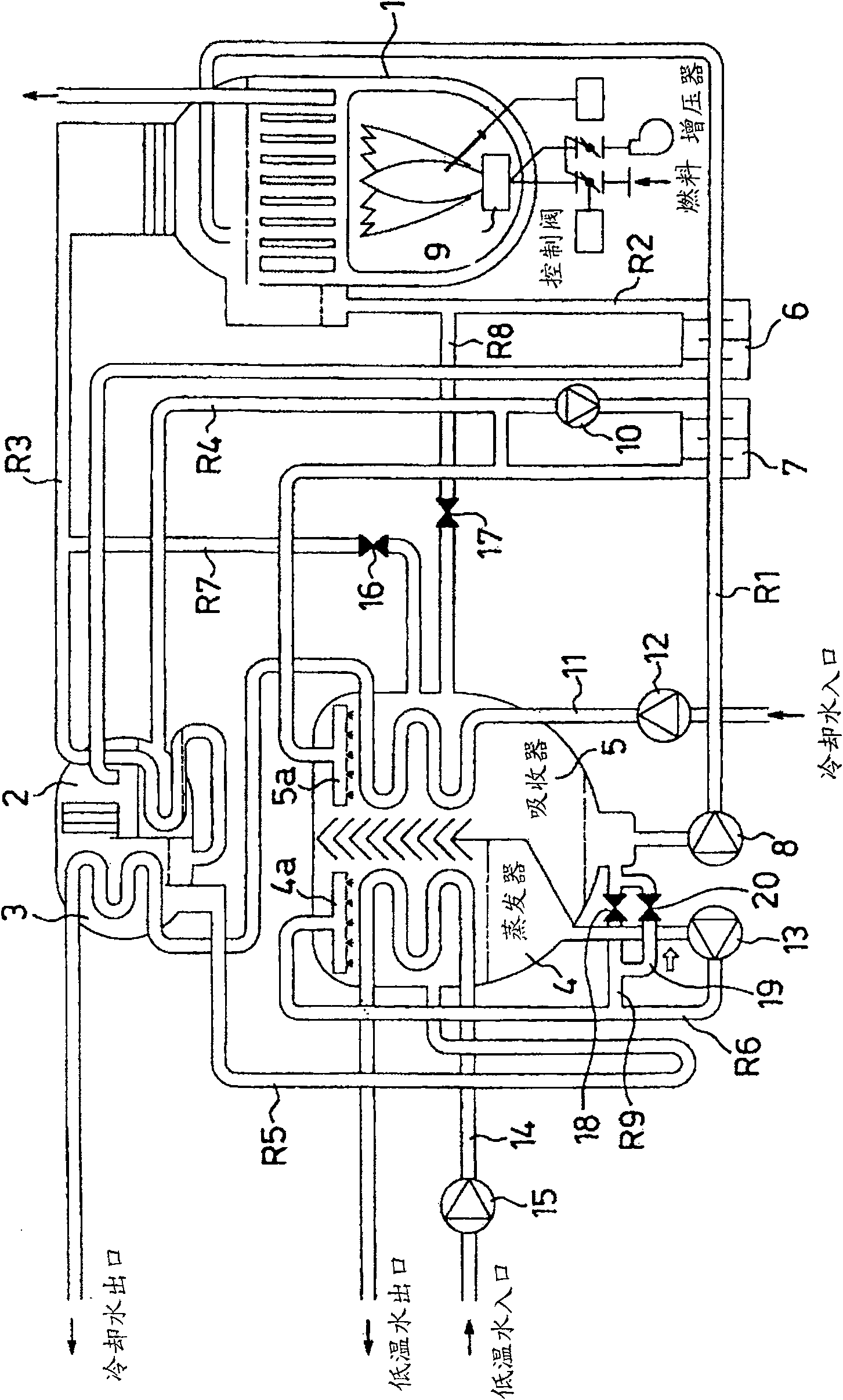
[0058] image 3 is a configuration diagram showing a second embodiment of the present invention. In this embodiment, components having the same structure as those in the first embodiment are given the same symbols as above, and detailed description thereof will be omitted. In this embodiment, it is characterized in that the refrigerant liquid pump 13 supplies the refrigerant liquid stored at the bottom of the evaporator 4 to the refrigerant liquid distribution pipe 4a provided on the upper part of the evaporator 4 in the pipeline R6 A refrigerant liquid bypass line 19 connecting the downstream side of the refrigerant liquid pump 13 and the bottom of the absorber 5 is provided, and an on-off valve 20 is provided on the refrigerant liquid bypass line 19 . In the illustrated example, the refrigerant liquid bypass line 19 is formed as a bypass line connecting the upstream side and the downstream side of the on-off valve 18 of the line R9 using the line R9. In addition, it is pre...
Embodiment 3
[0065] Figure 5 is a configuration diagram showing a third embodiment of the present invention. In this embodiment, components having the same structure as those in the first embodiment are given the same symbols as above, and detailed description thereof will be omitted. In this embodiment, it is characterized in that a cooling water bypass line 21 connecting the upstream side of the absorber 5 and the downstream side of the absorber 5 of the cooling water line 11 is provided, and the cooling water bypass line An on-off valve 22 is provided on the road 21 .
[0066] In this embodiment, when the cooling water pump 12 is started independently when the absorption chiller is stopped, the on-off valve 22 is opened to allow part of the cooling water to flow from the cooling water pump 12 through the cooling water bypass pipe with small flow path resistance. Road 21 flows. Therefore, it is possible to reduce the flow rate of the cooling water passing through the inside of the ab...
PUM
 Abstract
Description
Claims
Application Information
 - R&D
- Intellectual Property
- Life Sciences
- Materials
- Tech Scout
- Unparalleled Data Quality
- Higher Quality Content
- 60% Fewer Hallucinations
Browse by: Latest US Patents, China's latest patents, Technical Efficacy Thesaurus, Application Domain, Technology Topic, Popular Technical Reports.
© 2025 PatSnap. All rights reserved.Legal|Privacy policy|Modern Slavery Act Transparency Statement|Sitemap|About US| Contact US: help@patsnap.com


