Large power long range permanent magnetism synchronous linear motor servo drive apparatus

A permanent magnet synchronous linear and servo drive technology, which is applied to the reduction gear of AC motors, motor generators/starters, non-electric variable control, etc., can solve problems such as affecting system performance, increasing development costs, and increasing system costs. , to achieve the effect of improving security performance, solving startup problems, and meeting upgrade requirements

Inactive Publication Date: 2009-10-28
HUAZHONG UNIV OF SCI & TECH
View PDF3 Cites 0 Cited by
  • Summary
  • Abstract
  • Description
  • Claims
  • Application Information

AI Technical Summary

Problems solved by technology

DSP has fast computing speed, flexible control, and high level of intelligence, but it is used alone to complete all control and logic processing functions, resulting in low utilization of DSP and affecting system performance; at the same time, it is necessary to increase a large number of peripheral circuits, which means Inevitably increase the cost of the system, increase the complexity of the system, and it is not convenient to maintain the system; in addition, when the system needs to be upgraded or function expanded, the previously used peripherals and their interface circuits may not meet the needs and must be redeveloped, increasing Development costs are not conducive to system upgrades and system function expansion
Therefore, servo control systems based on DSP or FPGA have some shortcomings that cannot be overcome by themselves, and other methods must be used to solve them.

Method used


Image

  • Large power long range permanent magnetism synchronous linear motor servo drive apparatus
  • Large power long range permanent magnetism synchronous linear motor servo drive apparatus
  • Large power long range permanent magnetism synchronous linear motor servo drive apparatus

Examples


Embodiment Construction

[0018] The present invention will be described below in conjunction with the accompanying drawings and specific embodiments.

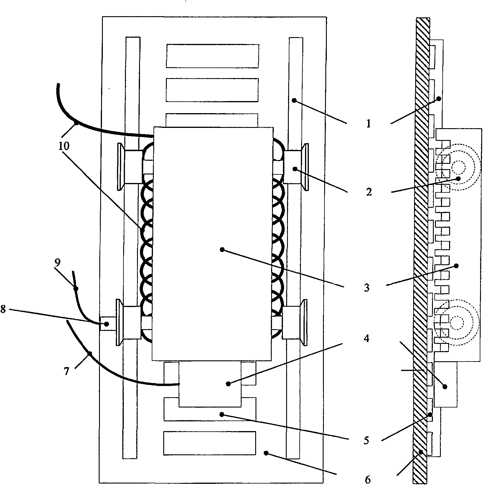
[0019] like figure 1 As shown, in this embodiment, the incremental rotary photoelectric encoder 8 is installed on the guide roller 2, the guide roller 2 and the motor mover 3 are fixed together, and move back and forth on the guide rail 1, and the linear motor stator permanent magnet 5 is fixed on the bottom plate 6. The A, A, B, B, Z, Z signals generated by the incremental photoelectric encoder 8 can be used to measure the rotation angle and rotation speed of the guide roller 2, and the rotation speed and rotation angle of the guide roller 2 are proportional to the speed and displacement of the motor mover 3. Proportional, so the speed and displacement of the motor mover 3 can be further obtained. A position sensor 4 including three Hall position sensors Hall1, Hall2 and Hall3 is installed at the end of the motor mover 3 . The armature power line 1...


PUM


Abstract

The invention provides servo-driving mechanism of a large power long stroke permanent magnetism synchronous linear motor, which principally includes an increment rotating optical-electricity encoder, a position sensor, a digital signal processor, a field programmable gate array and an intelligent power module. The increment rotating optical-electricity encoder and the position sensor are connected to the digital signal processor, for providing signals including rolling wheel rotation angle, rotary speed as well as motor rotor reference position information; the digital signal processor is connected to the intelligent power module through the field programmable gate array, for executing various operating command and vector control algorithmic calculation, and producing impulse-width modulation signals to transmit to the intelligent power module to complete the voltage inversion. The invention does not need expensive linear position detection device such as a grating ruler, a magnetic grid ruler, etc., which has features of low cost, good dynamic performance, large startup force moment, strong expandable capability, etc., and is especially suitable for applications situation of elevator, railcar transport, industry lift equipment, etc. driven by the large power long stroke permanent magnetism synchronous linear motor.

Description

technical field [0001] The invention relates to the technical field of AC motor servo control, in particular to a servo drive device for a high-power, long-stroke permanent magnet synchronous linear motor. Background technique [0002] At present, due to the limitation of linear motor mover position and speed detection methods and devices, the control of high-power, long-stroke permanent magnet synchronous linear motors mostly adopts V / F control or vector control without position sensor. [0003] V / F control belongs to open-loop control, based on the steady-state characteristics of the motor, it cannot accurately control the electromagnetic thrust, and cannot quickly achieve stability when the load changes suddenly. Vector control belongs to closed-loop control, based on the motor dynamic mathematical model decoupled by three-phase current, it can precisely control the electromagnetic thrust of the motor, and the motor responds quickly and has good stability. The permanent ...

Claims


Application Information

Patent Timeline
Patent Type & Authority Patents(China)
IPC IPC(8): G05D3/00G05D3/12H02P1/16H02P3/22
Inventor 陈学东曾理湛李小清农先鹏伞晓刚贾文川姜伟叶燚玺
Owner HUAZHONG UNIV OF SCI & TECH
Why Eureka
Try Eureka