Through wall device for screening wire of electromagnetic screening chamber

An electromagnetic shielding and network cable technology, applied in the direction of magnetic field/electric field shielding, electrical components, etc., can solve problems such as poor contact, difficulty in building structure and structured wiring technology, and reduced shielding performance, and achieve the effect of simple structure and process

Inactive Publication Date: 2009-12-02
上海俊悦光纤网络科技有限公司
View PDF5 Cites 2 Cited by
  • Summary
  • Abstract
  • Description
  • Claims
  • Application Information

AI Technical Summary

Problems solved by technology

This will cause great difficulty to the design of the computer room and the surrounding layout; for the installation and welding of shielded plug sockets, a large number of welding points also require high-level electronic assembly workers, which requires a long construction period, and a large number of welding points and The contact of the connector will reduce the reliability of the network connection and cause hidden dangers; at the same time, a shielded socket has at least one Φ22 hole and four Φ3.5 holes, and there will be 500 holes in terms of 100 wires, which is undoubtedly important for shielding performance. a threat
[0004] There is also a copper tube with a length of more than 20 meters for each shielded network cable to reduce electromagnetic wave leakage. There is also a funnel-type device filled with conductive copper shavings. These two devices have their own shortcomings. The first device is because 20 The layout of the meter-long copper casing brings great difficulties to the building structure and structured wiring technology, because it is impossible to leave the required large space when building the building or in the built building, because the wiring copper The space occupied by the bending of the tube will be larger; and the second device will cause poor contact due to the oxidation of copper scraps over time, which will reduce the shielding performance, and practice has proved that it can only be used for a small number of cables and cannot be used for Over the wall with hundreds of cables

Method used


Image

  • Through wall device for screening wire of electromagnetic screening chamber
  • Through wall device for screening wire of electromagnetic screening chamber

Examples


Embodiment approach

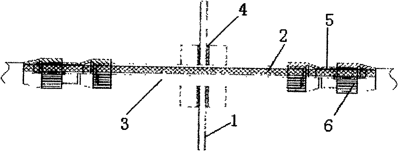
[0022] The embodiment that adopts threading waveguide of the present invention is as follows:

[0023] 1. Drill a fine-pitch screw hole with the same outer diameter as the waveguide on the wall plate, and polish off the anti-corrosion layer of the steel plate within 1cm around. If it is an autocratic copper-plated steel plate, it only needs to be cleaned with alcohol;

[0024] 2. Screw in the waveguide to the center position;

[0025] 3. Pad the gaskets made of 200-mesh copper mesh at both ends, and fix the two pressing pieces to make them compact;

[0026] 4. Strip the insulation of the network cable to expose the copper wire shielding layer, wrap it with 200-mesh copper wire mesh, and stuff it into the waveguide. The stripped length should exceed the length of the center chuck;

[0027] 5. Tighten the center chuck;

[0028] 6. Tighten the locking head.


PUM


Abstract

The invention relates to an electromagnetic shielding room shielding network wire passing wall device, which comprises a network shielding cable (2); a section of waveguide (3); the waveguide (3) passes through the shielding wall (1), and There are fixed copper mesh spacers (4) on both sides respectively; the network shielded cable (2) passes through the waveguide (3); at both ends of the waveguide (3), the network shielded cable (2) is made of copper The net (5) replaces the insulating sheath and is tightened by the center chuck (6); the beneficial effect of the present invention is: due to the use of shielding grounding and waveguide principles, a central waveguide with an outer diameter of 10 mm is used to pass through the central waveguide hole of the shielding steel plate and the shielding The outer diameter of the shielding layer of the network cable is matched, and the dressing is directly passed through the shielding steel plate. The structure and process are simple. In related projects, as many as 400 shielded network cables are used to pass through the wall, and the shielding performance reaches the corresponding confidentiality standards and military standards. Can achieve 100dB shielding effectiveness.

Description

technical field [0001] The invention relates to an electromagnetic shielding room, in particular to a wall-passing device for shielding network lines in the electromagnetic shielding room. Background technique [0002] With the requirements of information security technology, the shielded computer room of the information technology equipment built is faced with the problem of passing through the wall of a large number of network shielded cables (four pairs of twisted-pair shielded wires). Because for a shielding body, the shielding discontinuity caused by any opening or gap will directly affect its shielding performance, and generally there are a large number of shielded network cables that need to enter and exit such a computer room, up to several hundred. [0003] If the shielded plug socket is used for connection, a large number of relatively large holes will be opened on the side wall steel plate, and it will occupy a large area. This will cause great difficulty in the ...

Claims


Application Information

Patent Timeline
Patent Type & Authority Patents(China)
IPC IPC(8): H02G3/22H05K9/00
Inventor 唐荣喜赵铭谊
Owner 上海俊悦光纤网络科技有限公司
Why Eureka
Try Eureka