Supercharge Your Innovation With Domain-Expert AI Agents!

Clock signal detection circuit

A technology for detecting circuits and clock signals, applied in the direction of generating/distributing signals, monitoring pulse chain mode, etc., can solve the problems of operating temperature and input signal frequency changes, buffer delay time with process deviation, etc., to achieve the effect of reliable operation

Active Publication Date: 2009-12-09
SANECHIPS TECH CO LTD
View PDF6 Cites 0 Cited by
  • Summary
  • Abstract
  • Description
  • Claims
  • Application Information

AI Technical Summary

Problems solved by technology

[0007] The object of the present invention is a clock signal detection circuit proposed to solve the problem that the delay time of the buffer in the prior art changes with process deviation, operating temperature and input signal frequency

Method used


Image

  • Clock signal detection circuit
  • Clock signal detection circuit
  • Clock signal detection circuit

Examples


Embodiment Construction

[0031] A further detailed description will be given below in conjunction with specific implementations of the device of the present invention.

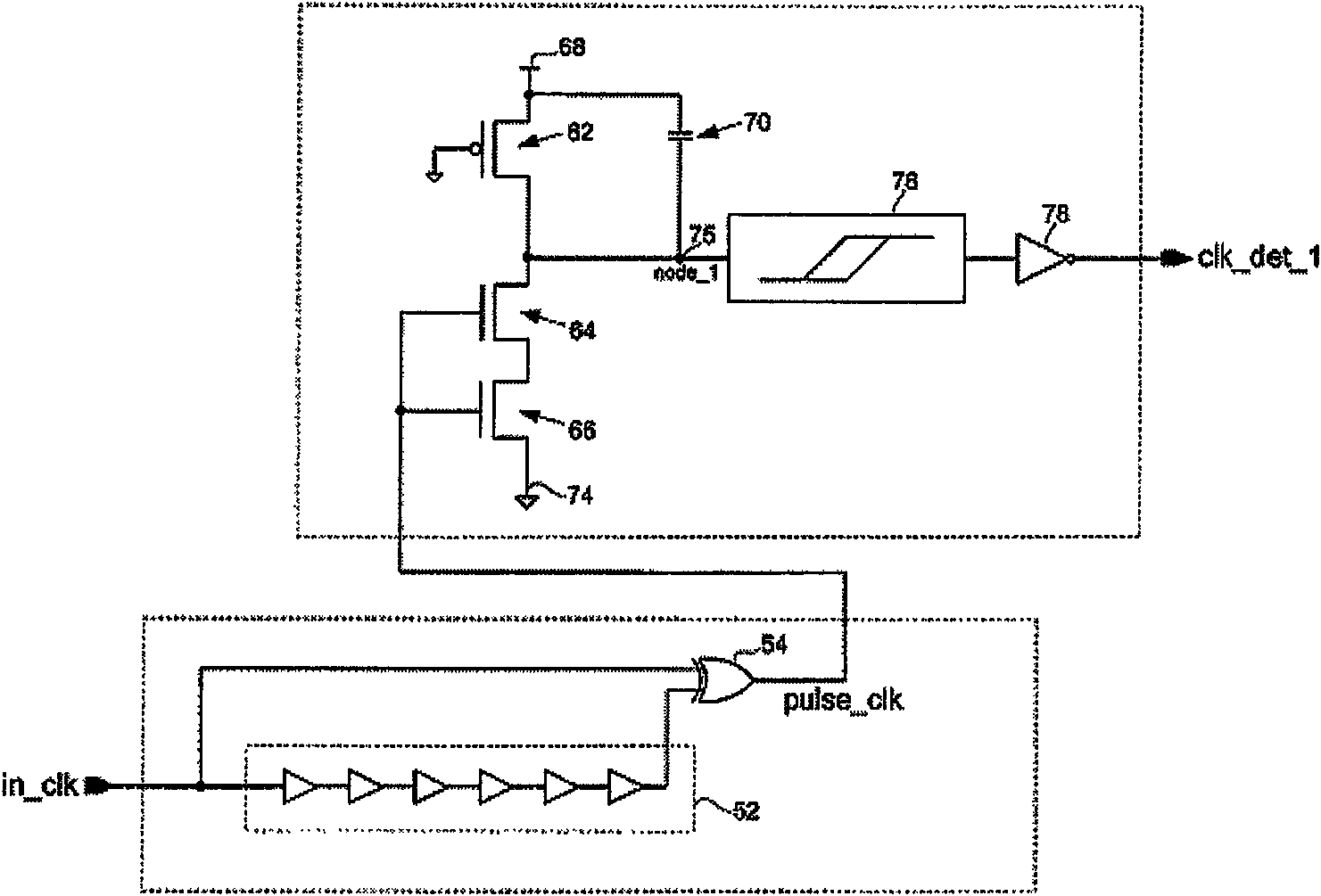
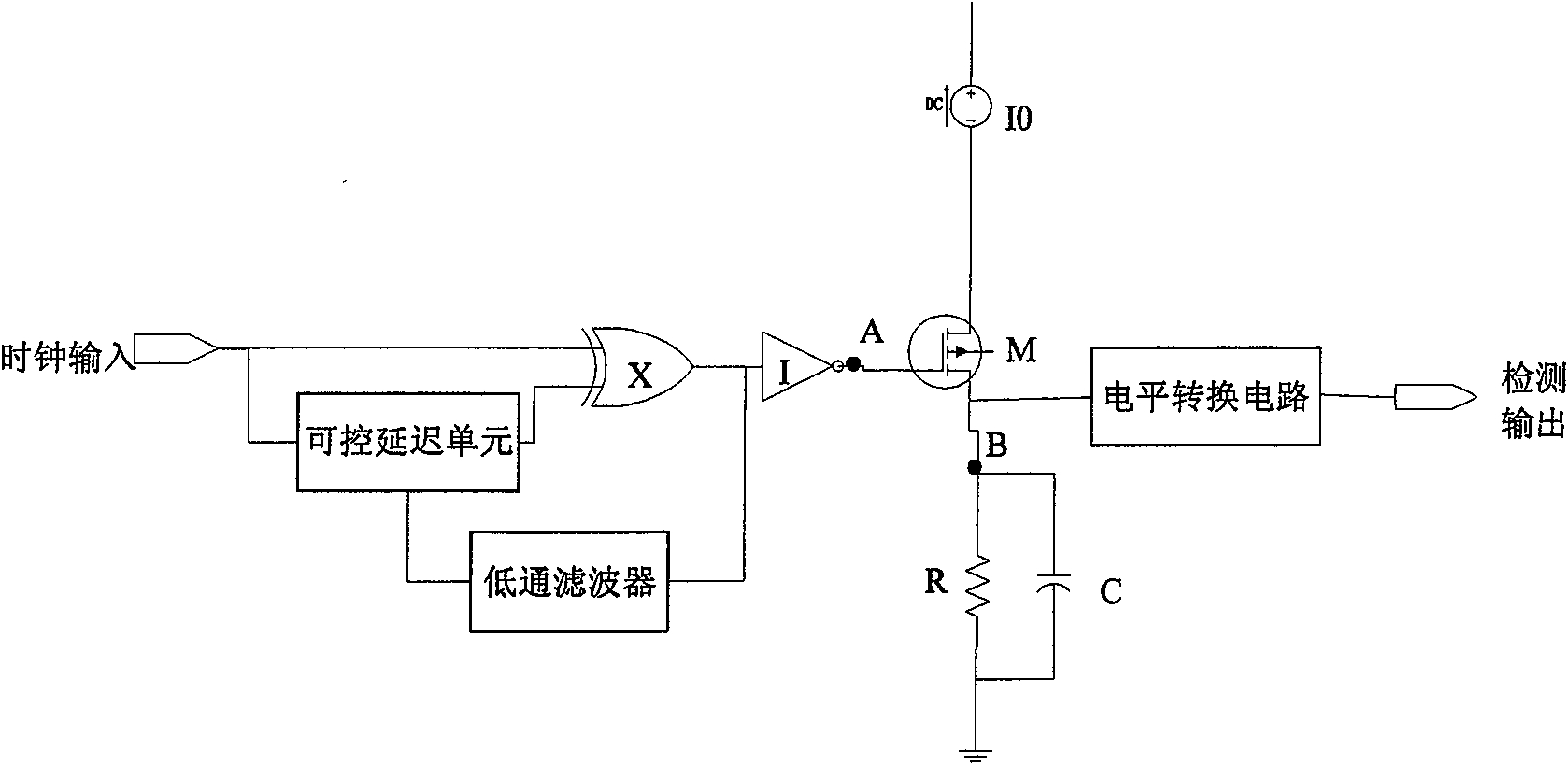
[0032] A clock signal detection circuit, including a voltage-controlled delay unit, an exclusive OR gate X, an inverter I, a low-pass filter, a PMOS transistor M, and a constant current source I 0 , resistor R, capacitor C and level conversion circuit, see the specific circuit figure 2 .

[0033] The specific connection of the clock signal detection circuit is as follows: the input clock is connected to the clock input terminal of the voltage-controlled delay unit and an input terminal of the XOR gate X at the same time, and the output of the voltage-controlled delay unit is connected to the other input terminal of the XOR gate X; The output of the gate is connected to the input of the inverter and the input of the low-pass filter at the same time, and the output of the low-pass filter is connected to the voltage control terminal of...


PUM


Abstract

The invention discloses a clock signal detection device, which comprises a voltage control delay unit, an exclusive OR gate, an inverter, a low-pass filter, a PMOS tube, a constant current source, a resistor, a capacitor and a level conversion circuit. The input clock is simultaneously connected to the clock input terminal of the voltage-controlled delay unit and one input terminal of the exclusive OR gate, and the output of the voltage-controlled delay unit is connected to the other input terminal of the exclusive OR gate; the output of the exclusive OR gate is simultaneously connected to the input of the inverter and The input terminal of the low-pass filter, the output terminal of the low-pass filter is connected to the voltage control terminal of the voltage control delay unit; the output of the inverter is connected to the gate of the PMOS transistor; the source terminal of the PMOS transistor is connected to the output of the constant current source, and the constant current source The other end of the current source is connected to the power supply; the drain end of the PMOS tube is connected to one end of the parallel resistor and capacitor and the input end of the level conversion circuit at the same time, and the other end of the parallel resistor and capacitor is grounded; the output of the level conversion circuit is the detection circuit. output.

Description

technical field [0001] The invention relates to the field of digital circuits, in particular to a clock signal detection circuit. Background technique [0002] In sequential logic digital circuits, the clock signal is a very critical signal. If the clock signal is lost or wrong, the functions of these digital circuits will not be realized, so it is necessary to detect this clock signal. When detecting the clock signal, if the commonly used sequential logic is used, it is necessary to provide an additional very reliable clock to serve the detection circuit. However, if it is implemented with a combinational logic circuit, no additional clock signal is needed, and the detection circuit works more reliably. [0003] In the detection circuit realized by combinatorial logic, the US Patent No. US6707320B2 provides a clock detection circuit, such as figure 1 shown. The clock signal is directly input to the XOR gate all the way, and then input to the other end of the XOR gate aft...

Claims


Application Information

Patent Timeline
Patent Type & Authority Patents(China)
IPC IPC(8): H03K5/19G06F1/04
Inventor 林满院
Owner SANECHIPS TECH CO LTD
Features
  • R&D
  • Intellectual Property
  • Life Sciences
  • Materials
  • Tech Scout
  • Unparalleled Data Quality
  • Higher Quality Content
  • 60% Fewer Hallucinations
Learn More