
Multi-laminar flow cribriform-plate-free boiling chloridization furnace

A boiling chlorination furnace, no sieve plate technology, applied in the direction of titanium halide, chemical instruments and methods, chemical/physical process, etc. The effect of easy temperature control, long running time and convenient operation

Inactive Publication Date: 2009-12-16
ZUNYI TITANIUM
View PDF3 Cites 0 Cited by
  • Summary
  • Abstract
  • Description
  • Claims
  • Application Information

AI Technical Summary

Problems solved by technology

[0002] At present, domestic and foreign chlorination methods mostly use boiling chlorination furnaces with sieve plates. The advantages are that the fluidized bed in the furnace is stable, easy to control, simple in equipment, and easy to make. Ditching makes the production index worse, and even forced to shut down the furnace, so the requirements for titanium-containing materials (natural rutile, artificial rutile, high-titanium slag, etc.), especially the requirements for calcium and magnesium impurities are relatively high
my country is a country with rich titanium resources. 95% of titanium ore is rock ore, which contains high impurities such as magnesium and calcium. The high-titanium slag produced by electric arc furnace smelting generally contains 7-10% Mgo+Cao, and is produced in the chlorination process. Magnesium and calcium chlorides are in a molten state at normal operating temperature, which is easy to block the holes of the sieve plate, so that the production cannot be carried out normally. The furnace must be shut down to replace the sieve plate. The replacement cycle is frequent, usually once every 20 to 30 days, and the labor intensity is high. The operation is dangerous, which seriously restricts the production of boiling chlorination

Method used


Image

  • Multi-laminar flow cribriform-plate-free boiling chloridization furnace
  • Multi-laminar flow cribriform-plate-free boiling chloridization furnace

Examples


Embodiment 1

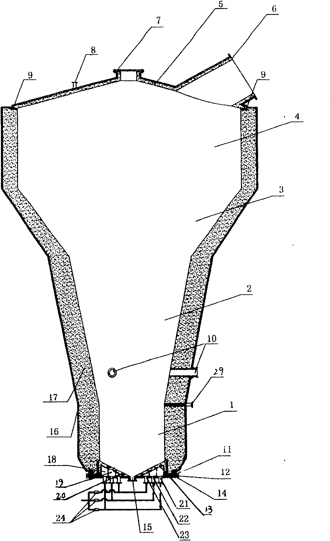
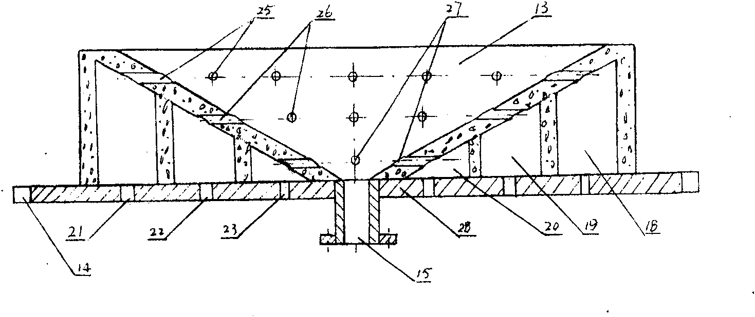
[0012] figure 1 It is a cross-sectional view of the multilayer flow fluidized chlorination furnace without sieve plate of the present invention. The furnace body of the chlorination furnace is cylindrical and conical, and is composed of an outer steel shell 16 and a furnace lining 17 lined with refractory materials. The furnace cover 5 is an inverted cone , the furnace cover 5 is equipped with a gas outlet 6, an explosion-proof port 7, and a temperature measuring port 8. The connection between the furnace cover 5 and the furnace body is a self-weight compression connection, and the joint is sealed with a refractory gasket 9, and the furnace body is from bottom to top Divided into four sections, the first furnace section 1 is conical, its upper part is equipped with a temperature measuring port 29, and its lower part has a flange 11 and a furnace bottom flange 14 fastened to the furnace bottom 13 with bolts. There is an elastic sealing ring 12 between the flanges 14 of the bott...


PUM


Abstract

Body of furnace of the present invention can be divided into four sections, the first furnace section (1) bottom has flange (11) and the flange (14) of furnace bottom fastening connection with furnace bottom (13) with bolt, the second furnace section ( 2) is conical, the third furnace section (3) is also conical, the fourth furnace section (4) is cylindrical, and the bottom of the furnace (13) is an integral three-layer chlorine gas storage chamber structure, at the bottom of the furnace (13) There is a conical chlorine gas storage chamber made of refractory concrete on the steel plate (28) of the bottom plate of the furnace. The outlets are connected with the chlorine pipes respectively, and each chlorine pipe is equipped with an automatic chlorine gas flow regulator (24), and the middle part of the furnace bottom (13) is provided with a slagging hole (15). The present invention changes the problem that the bottom of the original sieve boiling chlorination furnace has a short service time and is easy to be blocked, and is not suitable for high-titanium slag with high calcium and magnesium content, and improves the life of the bottom of the furnace, which can be extended by 5-7 months. The scope of application of chlorinated titanium-containing materials is broadened.

Description

technical field [0001] The invention relates to the preparation of titanium tetrachloride, in particular to a boiling chlorination furnace. Background technique [0002] At present, domestic and foreign chlorination methods mostly use boiling chlorination furnaces with sieve plates. The advantages are that the fluidized bed in the furnace is stable, easy to control, simple in equipment, and easy to make. Channeling will deteriorate the production index and even force the furnace to be shut down. Therefore, the requirements for titanium-containing materials (natural rutile, artificial rutile, high-titanium slag, etc.), especially the requirements for calcium and magnesium impurities are relatively high. my country is a country with rich titanium resources. 95% of titanium ore is rock ore, which contains high impurities such as magnesium and calcium. The high-titanium slag produced by electric arc furnace smelting generally contains 7-10% Mgo+Cao, and is produced in the chlori...

Claims


Application Information

Patent Timeline
Patent Type & Authority Patents(China)
IPC IPC(8): B01J8/18C01G23/02
Inventor 朱卫平时永华程代松余家华牟明刘义罗开元商金尚
Owner ZUNYI TITANIUM
Learn More