Honeycomb-type grating filler automatic filling device

A filling and honeycomb technology, which is applied in a device field of medical tumor radiotherapy equipment, can solve the problems of intensity-modulated conformal field performance and quality discount, poor treatment efficiency, and low image follow-up rate.

Inactive Publication Date: 2009-12-23
王乔生
View PDF3 Cites 0 Cited by
  • Summary
  • Abstract
  • Description
  • Claims
  • Application Information

AI Technical Summary

Problems solved by technology

[0005] However, the motorized multi-leaf collimator is composed of many independent tungsten alloy sheets and micro-motors overlapping together. First of all, it is limited by its structure and size, and the field of view cannot be exactly consistent with the shape of the tumor. The conformal field is obviously very rough. ;In addition, the thin slices need to move flexibly, therefore, the blades cannot be too close together, which will inevitably cause the leakage of rays through the gap between the blades, which greatly reduces the performance and quality of the intensity-modulated conformal field; Third, the tungsten alloy blade is driven by a stepping motor, and it takes time to move. In the image-guided intensity modulation conformal, it is impossible to adopt a more advanced way of beam following the movement of the organ. Only the treatment bed following technology can be used. The corresponding following speed will be affected
[0006] As mentioned above, the use of multiple radiation sources and multiple sets of multi-leaf grating collimator devices will make the structure of the radiotherapy equipment complex, and its image follow-up rate is low, making the treatment efficiency poor; and the safety of radiotherapy is not high, and the treatment effect is poor

Method used


Image

  • Honeycomb-type grating filler automatic filling device
  • Honeycomb-type grating filler automatic filling device
  • Honeycomb-type grating filler automatic filling device

Examples


no. 1 example

[0019] The present invention provides the first embodiment, refer below in conjunction with figure 1 , figure 2 , image 3 and Figure 4 The first embodiment will be described in detail.

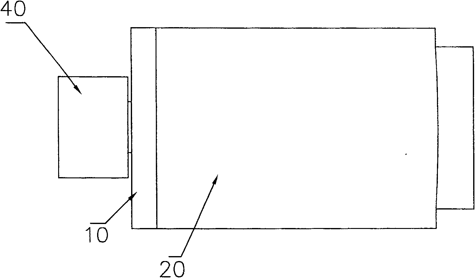
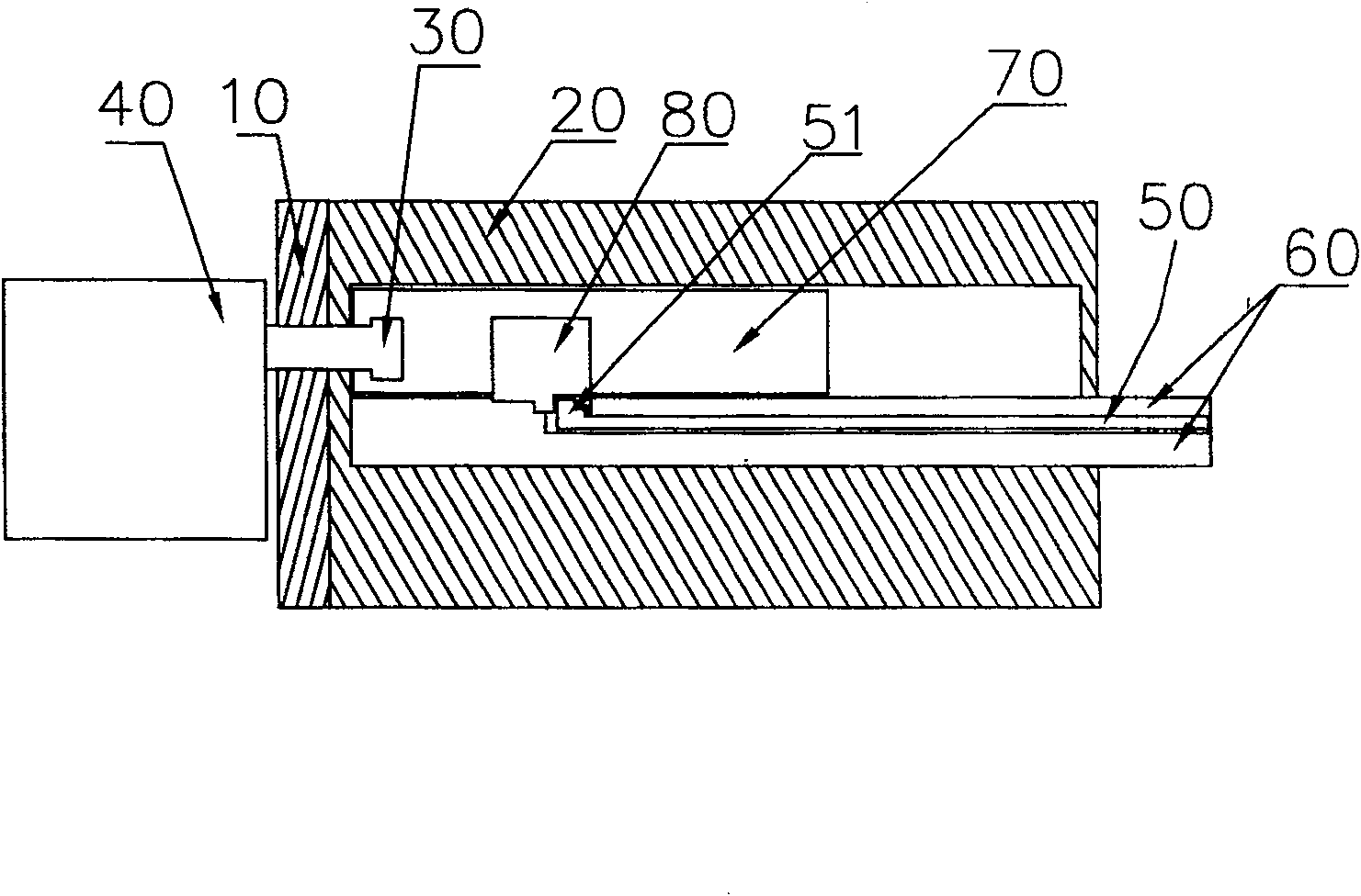
[0020] Such as figure 1 and figure 2 As shown, the honeycomb grating filling automatic installation device provided by the first embodiment includes a support 10 , a housing 20 , a push rod assembly, a driving rod 30 and a cylinder 40 . Wherein, the housing 20 is arranged on the support 10, and the housing 20 has a receiving cavity inside, and the receiving cavity communicates with the outside world. The push rod assembly is accommodated in the housing cavity of the housing 20 , and the push rod assembly includes a push rod protection and guide mechanism 60 , a push rod 50 , a clutch control mechanism 80 and a sliding guide mechanism 70 . The push rod guarding mechanism 60 is fixed in the receiving cavity of the housing 20 , the push rod 50 is slidably stored on the push rod guarding...

no. 2 example

[0023] The present invention provides a second embodiment, which is combined below Figure 5 , Figure 6 and Figure 7 Describe in detail.

[0024] The automatic installation device for honeycomb grating filler provided by the second embodiment includes two sets of push pin assemblies, and also includes a partition 90 . Each push pin assembly includes a push rod protection guide mechanism 60 , a plurality of push rods 50 , a sliding guide mechanism 70 and a plurality of clutch control mechanisms 80 . Such as Figure 5 As shown, the partition 90 is arranged in the center of the housing cavity 20, and the two sets of push pin assemblies are independently and symmetrically arranged on both sides of the partition 90, and the sliding guide mechanism 70 of each push rod assembly is in line with the described The drive rod 30 is connected. Please combine Figure 6 As shown, in the second embodiment, a plurality of clutch control mechanisms 80 are included, and these clutch cont...


PUM


Abstract

The invention discloses a honeycomb type grating filler automatic loading device, which includes a support, a housing, a push rod assembly, a drive rod and a cylinder, wherein the housing is arranged on the support, and there is a storage cavity inside the housing, and the push rod assembly accommodates In the storage cavity, the push rod assembly includes a push rod guard and guide mechanism, a push rod, a clutch control mechanism and a sliding guide mechanism. The push rod guard and guide mechanism is fixed in the storage cavity, and the push rod is slidably stored on the push rod guard and guide mechanism , the clutch control mechanism is set on the sliding guide mechanism, and the clutch control mechanism is slidably arranged in the storage cavity along with the sliding guide mechanism. The sliding guide mechanism is connected with the driving rod, and the driving rod is connected with the cylinder. Connection or separation, when the clutch control mechanism is connected with the push rod, it drives the push rod to move together. The present invention can automatically and selectively control the movement or non-movement of the push rod, thereby automatically and selectively pushing the filler into the honeycomb grating.

Description

technical field [0001] The invention relates to a medical treatment instrument, in particular to a device of a medical tumor radiation treatment instrument. Background technique [0002] Traditional radiation therapy equipment includes central processing control device, treatment bed, treatment host, power supply and signal transmission device, electric cabinet control device, etc. Among them, the treatment host includes a drum, which is equipped with an X-ray generating device for helical tomography and an image acquisition and receiving device, as well as a radiation source, a grating and a collimator device for radiation therapy, as well as a device for detecting the effect of radiation therapy and Dose detection device for radiotherapy progress, etc. [0003] Among them, the radiation source device, the grating and the collimator device are key components, which are related to the overall structural arrangement of the radiation therapy instrument and the effect and effi...

Claims


Application Information

Patent Timeline
Patent Type & Authority Patents(China)
IPC IPC(8): A61N5/10A61N5/00G21K1/02G21K1/04G02B5/18G02B27/00
Inventor 王乔生郝镇熙李发军
Owner 王乔生
Why Eureka
Try Eureka