
Analog ultrasonic wave earthquake signal physical excitation and receiving system and method thereof

A seismic signal and receiving system technology, applied in the field of ultrasonic detection, can solve the problems of strong shallow reflection signal, low accuracy, and distortion of received signal, achieve significant economic and social benefits, solve the distortion of received signal, and solve the problem of accuracy low effect

Active Publication Date: 2009-12-23
CHINA PETROLEUM & CHEM CORP +1
View PDF7 Cites 0 Cited by
  • Summary
  • Abstract
  • Description
  • Claims
  • Application Information

AI Technical Summary

Problems solved by technology

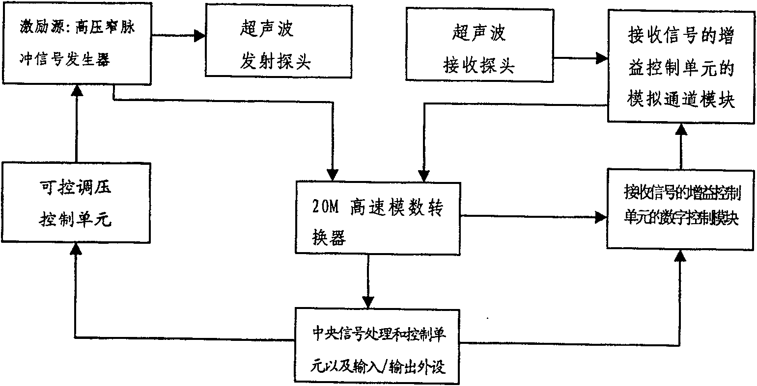
[0009] 1. The pulse generator in the excitation source cannot quantitatively control the high and low amplitude of the pulse signal emission, resulting in technical problems of low accuracy and distortion: For different channel signals, in order to reflect the reflected signal of the longer channel, it is necessary to output the signal from the signal source Turn it up, but the reflection near the channel is too strong at this time, and the output will be cut off, which will cause saturation distortion-distortion
When the output signal of the signal source is small, the reflection near the channel is normal, but the reflection of the far channel cannot be reflected because the signal is too small
That is, it is impossible to quantitatively control the amplitude of the high-voltage narrow pulse output at the signal transmitting end according to actual needs
[0010] 2. The amplifier in the receiving end cannot be amplified according to the different changes in energy absorption and reflection of each stratum, resulting in technical problems of low accuracy and distortion of the received signal: for the same signal, the transmitted signals of the deep layer and the shallow layer are different. Yes, under normal circumstances, the deep reflection signal is weak and the shallow reflection signal is strong
In order to make the deep reflection large enough, the amplification factor of the amplifier needs to be increased, but at this time, the shallow reflection signal will be too strong, and the output will be clipped-distorted; otherwise, the deep layer signal will not come out if the amplification factor of the amplifier is reduced -distortion

Method used


Image

  • Analog ultrasonic wave earthquake signal physical excitation and receiving system and method thereof
  • Analog ultrasonic wave earthquake signal physical excitation and receiving system and method thereof
  • Analog ultrasonic wave earthquake signal physical excitation and receiving system and method thereof

Examples


Embodiment Construction

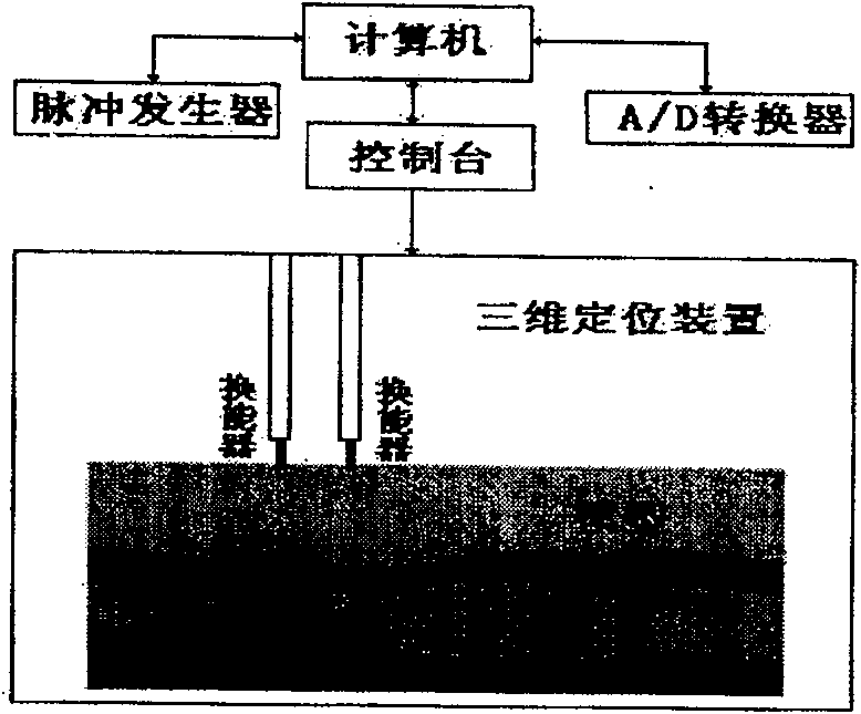
[0056] figure 1 It is a schematic diagram of the main structure of the ultrasonic transmission / reception detection system in the prior art

[0057] At present, ultrasonic testing devices are often used in geophysical laboratories for ultrasonic testing of geological models. The main parts of the device are:

[0058] 1. Excitation source (pulse generator): output high-voltage narrow pulse to drive the ultrasonic transmitting probe;

[0059] 2. Ultrasonic transmitting probe: It converts high-voltage narrow pulse signal into ultrasonic signal and transmits it to the object under test. Geologically, a firing position is usually called a shot point;

[0060] 3. Ultrasonic receiving probe: It converts the received ultrasonic signal into a voltage signal. Geologically, a receiving point position is usually called a track, and each track usually collects 6,000 data within 0.3 milliseconds, and each data is usually 24 bits;

[0061] 4. Amplifier: Amplify the weak voltage signal sen...


PUM


Abstract

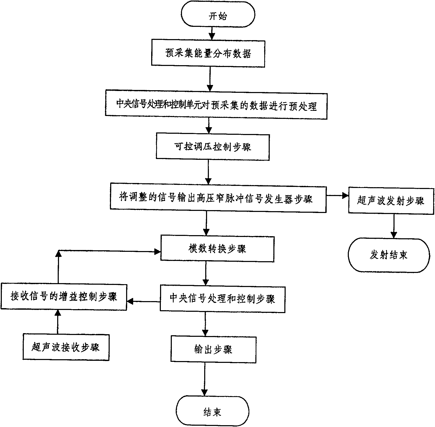
The present invention relates to a physical excitation and reception system and a method for simulating ultrasonic seismic signals. Including excitation source, ultrasonic transmitting probe, ultrasonic receiving probe, analog-to-digital converter, amplifier, central signal processing and control unit, and input / output peripheral unit; also includes controllable voltage regulation control unit and setting set in the signal excitation source Gain control unit of the received signal at the signal receiving end. The present invention quantitatively controls the emission energy and the reception gain, so as to meet the needs of the observation of complex multi-layer physical models in the laboratory. That is, on the one hand, the present invention adds a quantitative control pulse signal emission step and structure in the excitation source, so that the amplitude of the emission energy can be quantitatively controlled. The step and structure of quantitatively controlling the magnification are added to the amplifier in the invention, which solves the technical problems of low accuracy and distortion of the received signal in the prior art.

Description

Technical field: [0001] The invention relates to an ultrasonic transmitting and receiving detection device and a method thereof, in particular to a laboratory acquisition device and a method for performing ultrasonic detection and detection on geological models when simulating field seismic exploration under laboratory conditions, belonging to the field of ultrasonic detection . Background technique: [0002] Seismic physical simulation is an effective experimental technique for petroleum exploration and development. It is a scientific research method carried out on the basis that the geometric parameters and physical parameters of the model medium satisfy the similarity ratio principle and the correspondence principle. Modern seismic physical simulation is a kind of seismic simulation method in which the field geological structures and geological bodies are made into physical models according to a certain simulation ratio in the laboratory, and the field seismic exploratio...

Claims


Application Information

Patent Timeline
Patent Type & Authority Patents(China)
IPC IPC(8): G08C19/16G08C19/00G01V1/22G01V1/28
Inventor 赵群宗遐龄马国庆
Owner CHINA PETROLEUM & CHEM CORP
Learn More