Composite type cold slag device

A slag cooling device and composite technology, applied in the field of slag cooling device, can solve the problems of affecting combustion in the furnace, insufficient output, insufficient cooling of large slag, etc., and achieve the effect of enhancing cooling effect, improving adaptability, and ensuring output effect

Inactive Publication Date: 2010-01-20
CHONGQING UNIV
View PDF5 Cites 1 Cited by
  • Summary
  • Abstract
  • Description
  • Claims
  • Application Information

AI Technical Summary

Problems solved by technology

These existing technologies have one or more of the following shortcomings in design and operation: too large a proportion of air cooling, poor fluidity of bottom slag, insufficient cooling of large slag, poor recovery of fine particles, etc., resulting in frequent occurrences in actual operation. Problems such as clogging, coking, insufficient output, and affecting combustion in the furnace cannot meet the needs of actual operation and large-scale development of circulating fluidized bed boilers

Method used


Image

  • Composite type cold slag device
  • Composite type cold slag device
  • Composite type cold slag device

Examples


Embodiment 1

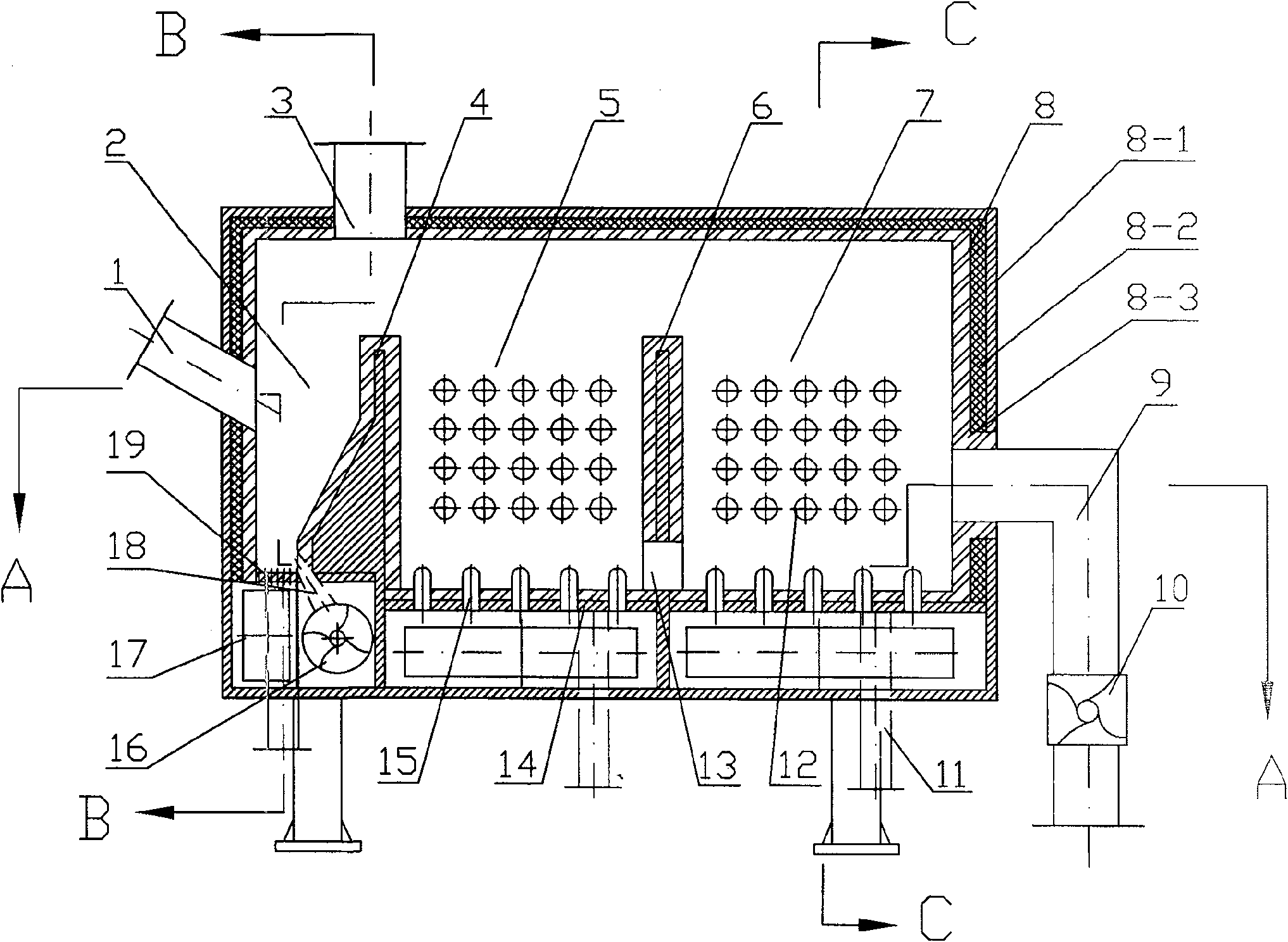
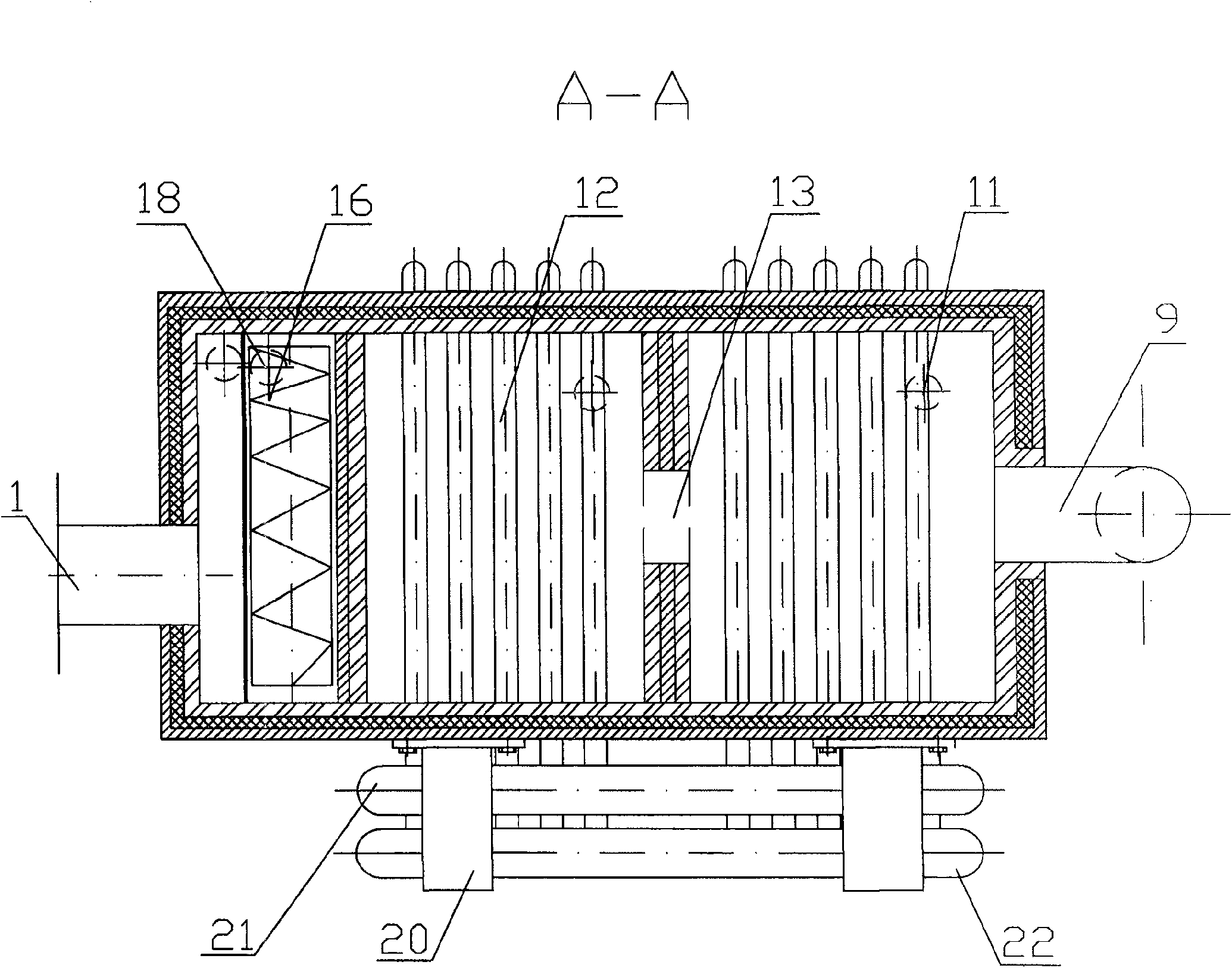
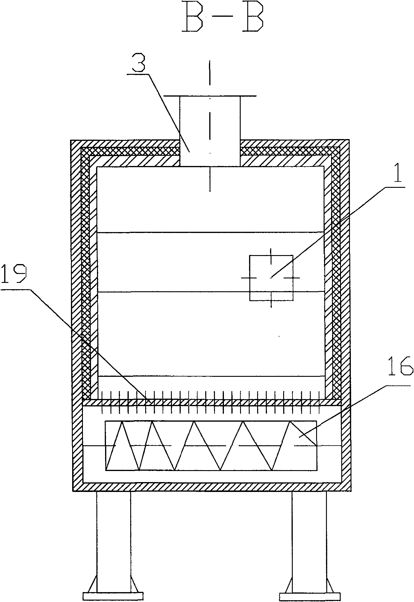
[0027] A kind of composite cold slag device of this embodiment such as figure 1 , figure 2 , image 3 and Figure 4 As shown, the frame 8-1 of the cold slag chamber 8 is welded into a square body by steel plates, angle steels, and channel steels, and is lined with an insulating layer 8-2 and a refractory layer 8-3. The vertical first partition wall 4 and the second partition wall 6, the first partition wall 4 and the second partition wall 6 divide the inner space of the cold slag chamber 8 into three cooling chambers connected to the upper part: the cooling chamber at the left end is slag The inlet cooling bin 2, the cooling bin in the middle is the first water-cooled cooling bin 5, and the cooling bin at the right end is the second water-cooled cooling bin 7; the lower part of each cooling bin is equipped with an independent air chamber 17. Among them, a dense-hole air distribution plate 19 is arranged on the left side of the bottom of the slag inlet cooling chamber, whic...

Embodiment 2

[0029] A kind of composite cold slag device of this embodiment such as Figure 5 , Figure 6 and Figure 7As shown, the structural difference from Example 1 is that the cold slag chamber 8 in the cold slag device has four components, consisting of a frame 8-1, an insulation layer 8-2, a refractory layer 8-3, and a membrane water wall 8. -4 composition. The surrounding walls of the slag inlet cooling chamber 2 and the walls of the slag inlet and outlet are all frame 8-1 structures. The frame 8-1 is welded by steel plates, angle steels, and channel steels, and is lined with insulation layer 8-2 and refractory layer 8-3 ; And the front and rear walls and the upper wall of the first water-cooled cooling chamber 5 and the second water-cooled cooling chamber 7 are all made of membrane water-cooled wall 8-4, and membrane-type water-cooled wall 8-4 is welded and connected with frame 8-1. The arrangement of the membrane water wall 8-4 increases the heating surface of the entire slag...

Embodiment 3

[0031] A kind of composite cold slag device of this embodiment such as Figure 8 As shown, the structural difference from Example 1 is: in the structural arrangement of the slag inlet cooling bin 2, the densely porous air distribution plate 19 is located at the center of the bottom of the slag inlet cooling bin 2, and the area of ​​the densely porous air distribution plate 19 is the same as The area ratio of the cross-section of the upper straight section of the slag inlet cooling chamber 2 is 0.2 to 0.7. The upper part of the dense-hole air distribution plate 19 is arranged with a straight opening acceleration section and inclined end faces on the left and right sides. The main large slag discharge pipe 18 is arranged in a dense-hole type On the air distribution plate 19, a corresponding variable-pitch water-cooled auger slag cooler 16 is arranged at the outlet. Other structural arrangements and cooperation are the same as in Embodiment 1.

[0032] Each cooling chamber in th...


PUM


Abstract

The invention relates to combined type cold slag device. It includes cold slag room, air chamber, and water cooling packing auger cold slag machine. The cold slag room is set two divider to divide it into three cooling room. The second divider lower is set hole. The first cooling room is spouted bed structure of which bottom is set close-hole type grid plate on which the main slag discharge pipe is set. The back two cooling rooms are set water cooling tube bank, and funnel cap type grid plate at the bottom. The invention can satisfy the demands of big feeding coal granularity, actual motion and macro-scale operations technology development for circulating fluidized bed boiler.

Description

technical field [0001] The invention relates to a slag cooling device for a thermal power plant boiler, which is suitable for cooling the slag of a circulating fluidized bed boiler. Background technique [0002] At present, with the successful commercialization of several domestic 300MW-class circulating fluidized bed coal-fired boilers and the domestic 600MW supercritical circulating fluidized bed boiler entering the research and development stage, the process of circulating fluidized bed boiler technology to high-parameter large-scale is accelerating, and the boiler Important changes have taken place in the gas-solid flow characteristics in the furnace, requiring the corresponding slag cooler to meet the requirements of high-parameter circulating fluidized bed boilers. In the future operation of large-scale slag coolers, the recovery of fine particles in slag discharge will be more important, and the heat transfer mode in the slag cooler will be changed from air cooling to...

Claims


Application Information

Patent Timeline
Patent Type & Authority Patents(China)
IPC IPC(8): F23B70/00F23B101/00
Inventor 卢啸风舒茂龙刘汉周陈玉良王伟林王军
Owner CHONGQING UNIV
Why Eureka
Try Eureka