Spacer flange for a machine tool

An intermediate flange and machine tool technology, applied in the field of intermediate flanges, can solve the problems of expensive structure and heavy weight, and achieve the effect of reducing material input, reducing weight, and high torsional rigidity

Active Publication Date: 2010-01-27
ROBERT BOSCH GMBH
View PDF3 Cites 0 Cited by
  • Summary
  • Abstract
  • Description
  • Claims
  • Application Information

AI Technical Summary

Problems solved by technology

The wall thickness of conventional constructions is determined here by the area subjected to the greatest load, which leads to unnecessary material input
The unfavorable consequence of this is that the construction is relatively expensive and bulky

Method used


Image

  • Spacer flange for a machine tool
  • Spacer flange for a machine tool

Examples


Embodiment Construction

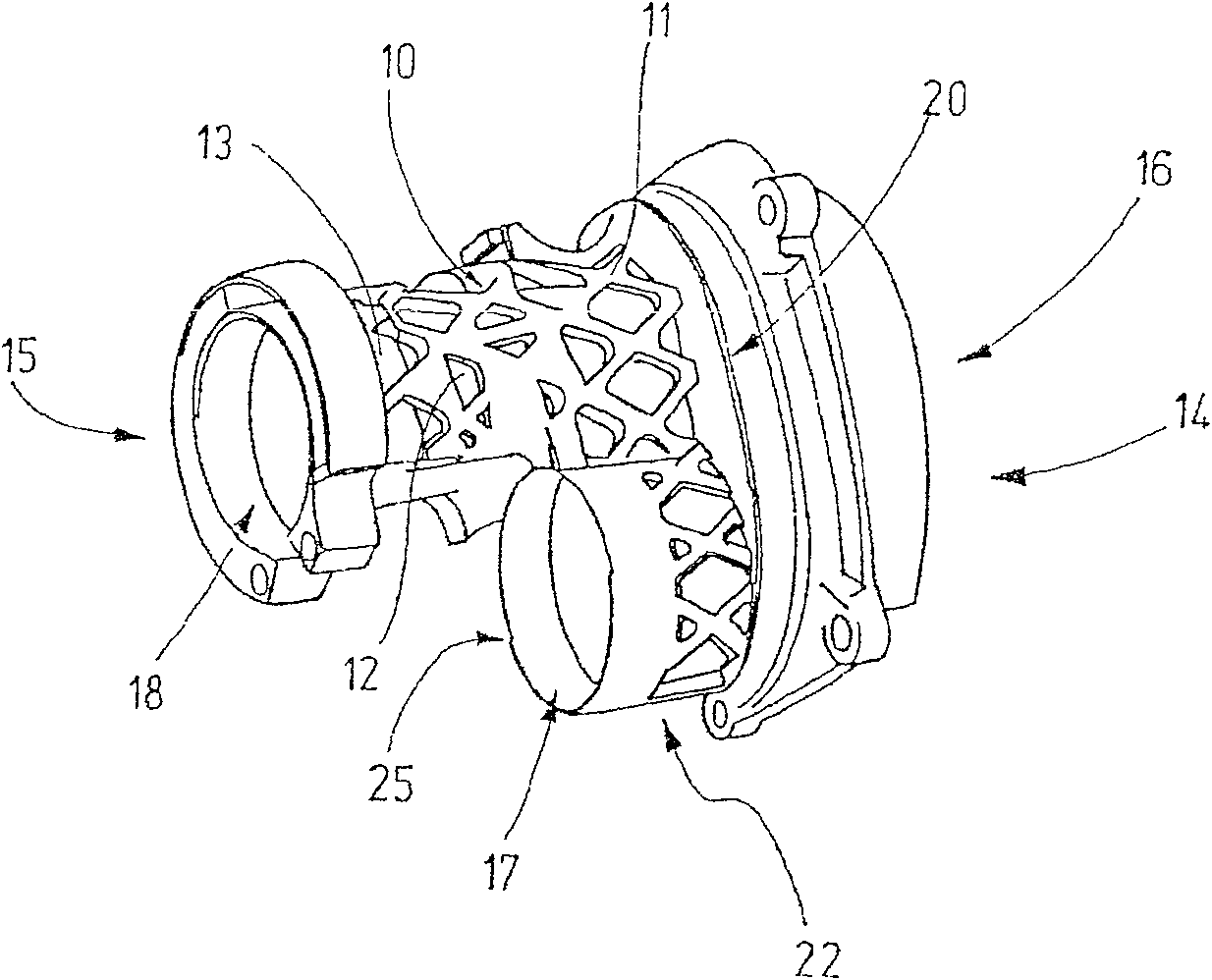
[0014] figure 1 Shows a perspective view of an embodiment of an intermediate flange according to the invention for a power tool, which is arranged in a housing (not shown) in the mounted state, in addition, in the housing There is also a drive motor (not shown), in particular an electric motor, a transmission and an impact device. The intermediate flange has an outer wall 22 with a grid-like support structure 10 having a regular, rhomboid structure. The support structure 10 is formed by solid webs 11 which intersect one another. Regions 12 located between webs 11 of the structure are filled with material, wherein these regions 12 of filling material are configured thinner-walled than webs 11 . For the sake of simplicity, only one of the webs 11 and one of the regions 12 is provided with reference numerals. Between the regions 12 of the filler material and the individual webs 11 there are in each case formed hollow spaces 13 which are open to the outside, so that a surface s...


PUM


Abstract

The invention relates to a spacer flange for a machine tool for the mounting of machine parts, comprising an outer wall (22). According to the invention, the outer wall (22) has a gridded support construction (10), giving said spacer flange a good torsional and bending resistance with low material requirements. The gridded support construction (10) can have a honeycomb or diamond-shaped structure with solid crossing webs.

Description

technical field [0001] The invention relates to an intermediate flange for a machine tool, which is used to support machine parts. Background technique [0002] Components designed as intermediate flanges for power tools, in particular for hammer drills and / or drill hammers of pistol design, are generally known, which are used for supporting the percussion device part and / or the motor shaft. The intermediate flange is preferably produced here from a heat-conducting material, for example from aluminum alloys, from magnesium, etc., and provides mechanical stability at relatively high operating temperatures. At the same time, heat is dissipated from the gear region by the structure and dissipated by the cooling air of the motor. The structures required here are relatively complex. In addition, conventional structures are produced using pressure casting techniques, in which a constant wall thickness is sought. The wall thickness of conventional constructions is determined her...

Claims


Application Information

Patent Timeline
Patent Type & Authority Patents(China)
IPC IPC(8): B25F5/02
CPCB25D17/00B25D2250/065B25D2250/121B25D2217/0061Y10T74/22Y10T74/14
Inventor 迪特马尔·绍尔
Owner ROBERT BOSCH GMBH
Why Eureka
Try Eureka