Side direction multilevel open type igniting center powder feeding vortex combustor of small oil mass gasification combustion

A swirling burner, open technology, applied in the direction of burner, burner, combustion method, etc. for burning powder fuel, can solve the problem of burning a large amount of pulverized coal, and achieve the reduction of smoke resistance and ignition energy Effect

Inactive Publication Date: 2010-01-27
HARBIN INST OF TECH
View PDF6 Cites 0 Cited by
  • Summary
  • Abstract
  • Description
  • Claims
  • Application Information

AI Technical Summary

Problems solved by technology

[0003] The purpose of the present invention is to solve the problem that when the existing micro-oil ignition swirl combustion device is applied to a large-capacity boiler, a large amount of pulverized coal needs to be ignited and a large-scale pulverized coal boiler using a swirl burner can reduce NOx emissions while the power plant boiler starts, To solve the problem of fuel saving in the case of stop and low-load stable combustion, we now provide a small oil volume gasification combustion side-to-side multi-stage open ignition center-feeding powder swirl burner

Method used


Image

  • Side direction multilevel open type igniting center powder feeding vortex combustor of small oil mass gasification combustion
  • Side direction multilevel open type igniting center powder feeding vortex combustor of small oil mass gasification combustion
  • Side direction multilevel open type igniting center powder feeding vortex combustor of small oil mass gasification combustion

Examples


specific Embodiment approach 1

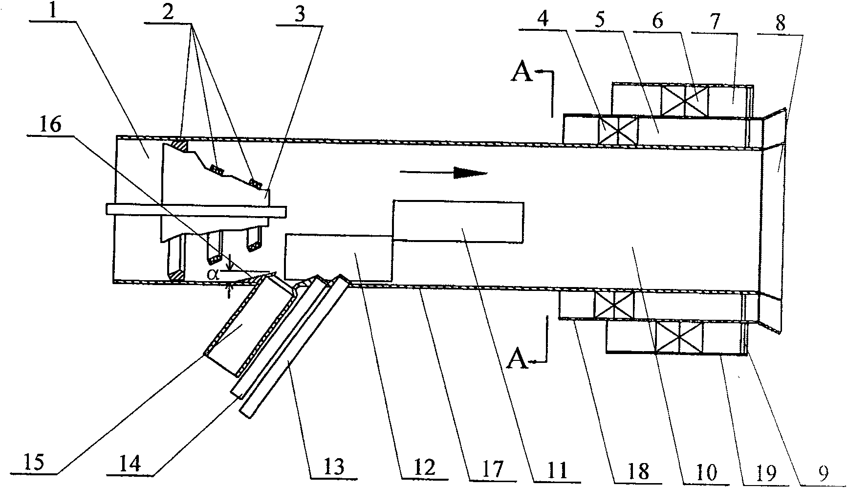
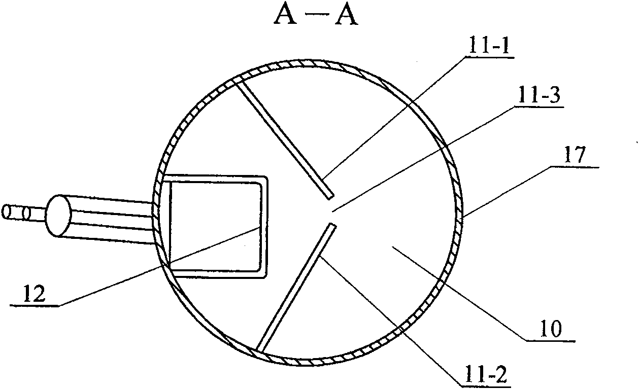
[0006] Specific implementation mode one: (see Figure 1 ~ Figure 2 ) This embodiment includes burner primary air duct 1, concentration ring 2, support plate 3, inner swirler 4, inner secondary air duct 5, outer swirler 6, outer secondary air duct 7, burner 8. Support rod 9, third-stage combustion chamber 10, second-stage combustion chamber 11, first-stage combustion chamber 12, main oil gun 15, block 16, first air duct pipe 17, second air duct pipe 18 and The third air duct pipe 19, the primary air duct 1 of the burner is inside the first air duct pipe 17, the outlet end of the first air duct pipe 17 is the burner 8, and the support plate 3 is fixed at the entrance of the first air duct pipe 17 end, the concentration ring 2 is fixed on the support plate 3, the first-stage combustion chamber 12 and the second-stage combustion chamber 11 are fixed in the first air duct pipe 17, and the first-stage combustion chamber 12 is fixed on the support plate 3 front end, the second-stage...

specific Embodiment approach 2

[0007] Specific implementation mode two: (see Figure 1 ~ Figure 2 ) The difference between this embodiment and the specific embodiment one is that it increases the auxiliary oil gun 13, the auxiliary oil gun 13 is arranged in parallel with the main oil gun 15, the auxiliary oil gun 13 communicates with the first-stage combustion chamber 12, and the auxiliary oil gun 13 is connected with the first-stage combustion chamber 12. The outlet end of the gun 13 is arranged in the middle of the combustion chamber 12 of the first stage. Others are the same as in the first embodiment.

specific Embodiment approach 3

[0008] Specific implementation mode three: (see Figure 1 ~ Figure 2 ) The difference between this embodiment and the specific embodiment two is that it has increased the flame detection device 14, and the flame detection device 14 is arranged between the auxiliary oil gun 13 and the main oil gun 15, and the flame detection device 14 and the first-stage combustion chamber 12 connected. Others are the same as in the second embodiment.

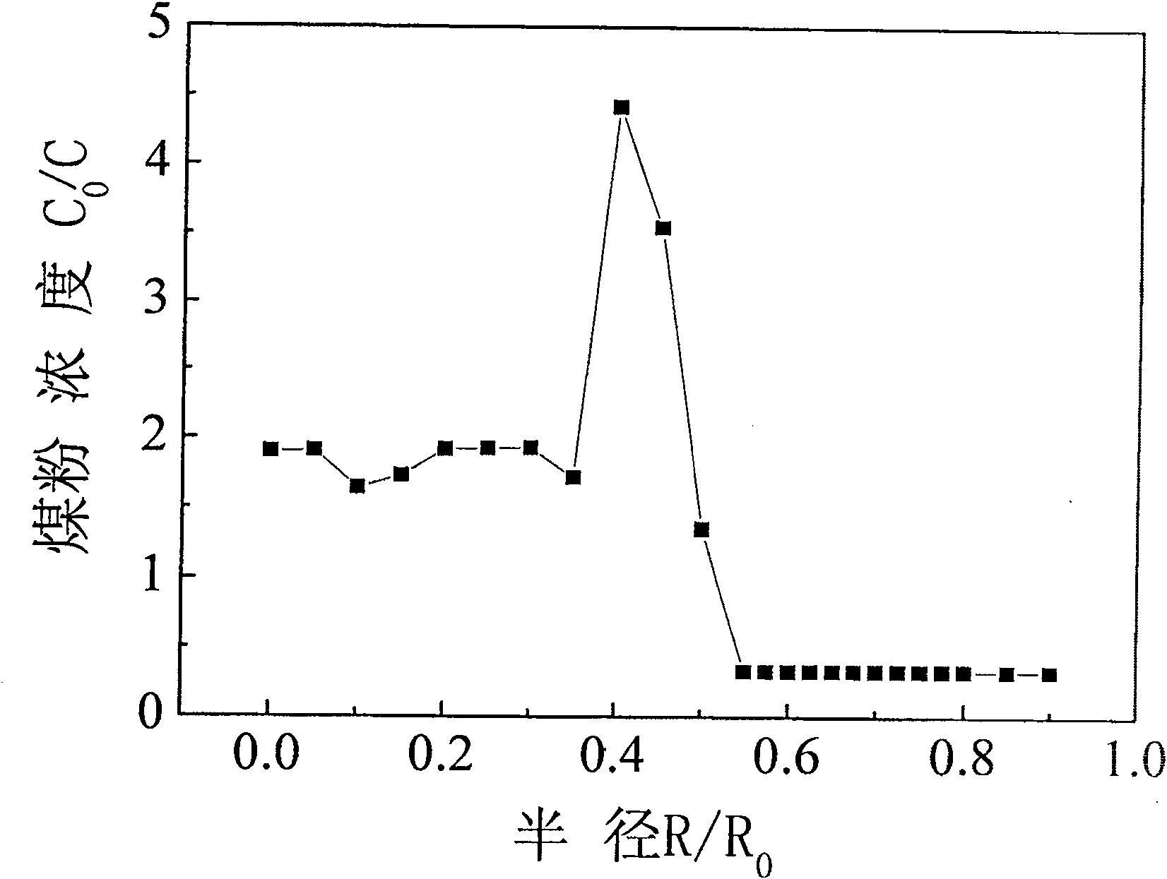
[0009] The pulverized coal is sent into the primary air duct 1 of the burner, and the pulverized coal is concentrated through the pulverized coal concentrator 2, and a high concentration of pulverized coal is formed in the central area of ​​the primary air duct 1 of the burner. The 600MW subcritical boiler is calculated by fluent software Concentration distribution results such as ( image 3 As shown), the high concentration area of ​​pulverized coal is in the center of the primary air duct 1 as the center of the 0.6R 0 Within, the rest is li...


PUM


Abstract

The invention discloses a low fuel-consumption gasified-combustion, side-multilevel open-ignition and central powder-supply turbulent burner which relates to the turbulent burner and aims at solving the problems about how to reduce the large quantity of coal powder to be ignited when the existing micro fuel-consumption ignition turbulent burner is applied to large-volume boilers, and how to conserve fuel consumed by a power-station boiler on the conditions that the boiler is started and stopped and works with low load when reducing the NOx discharged by a large-scale coal powder boiler adopting the turbulent burner. A first-class firebox of the invention is fixed in a first air-channel pipe at the front end of a support board; a second-class firebox is fixed in a first air-channel pipe at the front end of the first-class firebox; a third-class firebox is arranged in the first air-channel pipe at the front of the second-class firebox; a primary fuel-gun is communicated with a primary air channel of the burner. In the invention, the coal powder is combusted under a low oxygen reduction condition to prolong the stay time of the coal powder so as to control the generation of consumption-typed NOx. As the secondary air is divided into two pars of inner and outer, classified combustion is formed, low NOx discharge is realized and fuel is saved.

Description

technical field [0001] The invention relates to a swirl burner. Background technique [0002] In the existing large-capacity power plant boilers, the amount of oil used for boiler ignition and low-load stable combustion is huge. In order to save fuel, power generation companies shift the focus of fuel saving from the low-load stable combustion process to the boiler ignition and shutdown process (when the power plant boiler starts and stops Fuel consumption accounts for 60%, low-load stable fuel consumption accounts for 40%). According to the traditional method, the ignition oil gun is arranged in the secondary air port of the burner. The distance between the oil gun and the pulverized coal nozzle is relatively far, and the two airflows are parallel to each other. Therefore, the heat generated by the fuel oil is directly used for heating during ignition. The part of pulverized coal is relatively small, and the heat utilization rate is low, so that when the boiler is ignited,...

Claims


Application Information

Patent Timeline
Patent Type & Authority Patents(China)
IPC IPC(8): F23D1/02
Inventor 李争起陈智超刘春龙果志明孙绍增
Owner HARBIN INST OF TECH
Why Eureka
Try Eureka