
Gauge structure of single cone bit

A single cone and drill bit technology, which is applied in the direction of drill bits, drilling equipment, earthwork drilling, etc., can solve the problems of poor safety performance, inability to make the well wall smooth and smooth, and low practical value, and achieve the effect of reducing flow resistance

Active Publication Date: 2010-02-17
江西飞龙钻头制造有限公司
View PDF8 Cites 0 Cited by
  • Summary
  • Abstract
  • Description
  • Claims
  • Application Information

AI Technical Summary

Problems solved by technology

[0002] At present, the single cone bit used in petroleum, mining and geological drilling, when drilling, due to the rotation of the cone and the revolution around the centerline of the drill bit, the carbide teeth of the drill bit will cut the bottom of the well in a mesh shape, and at the same time form an arc. Inclined groove-shaped rough well wall, this kind of rough well wall reduces the effective section of the wellbore and threatens the safety of the drill bit. The deeper the well, the stricter the safety requirements for drilling. Therefore, there is no single tooth drill bit with gauge structure. The quality of the borehole is not high, the practical value is low, and the safety performance is poor. However, the existing single-cone bit gauge structure such as "a single-cone bit" in Chinese patent 98219946.5 is only provided on the bit body of the roller-cone bit. Gauge block, on which there are active cutting gage teeth and passive cutting gage teeth, the purpose of which is to protect the claw body of the roller cone bit from being overworn Wear and break, which affects the service life of the drill bit; it cannot effectively trim and cut the well wall of the drilled hole to make the well wall smooth and smooth; it cannot make the drilling quality of the drill bit meet the API hole diameter requirements

Method used


Image

  • Gauge structure of single cone bit
  • Gauge structure of single cone bit
  • Gauge structure of single cone bit

Examples


Embodiment Construction

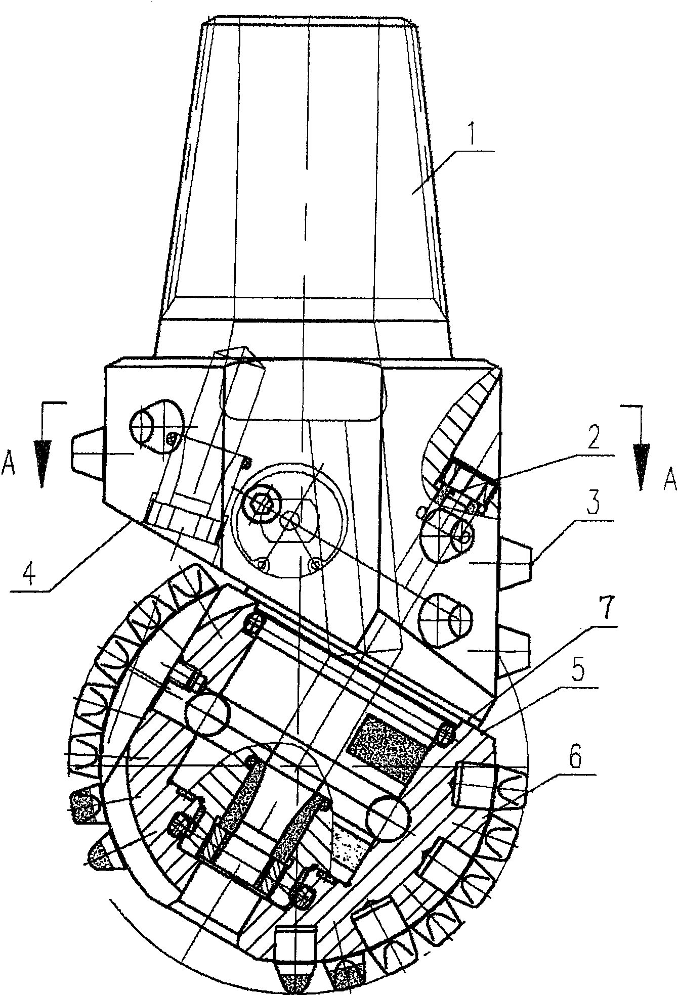
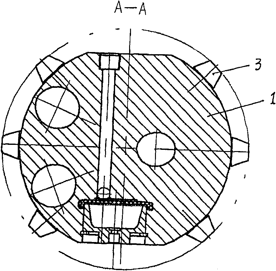
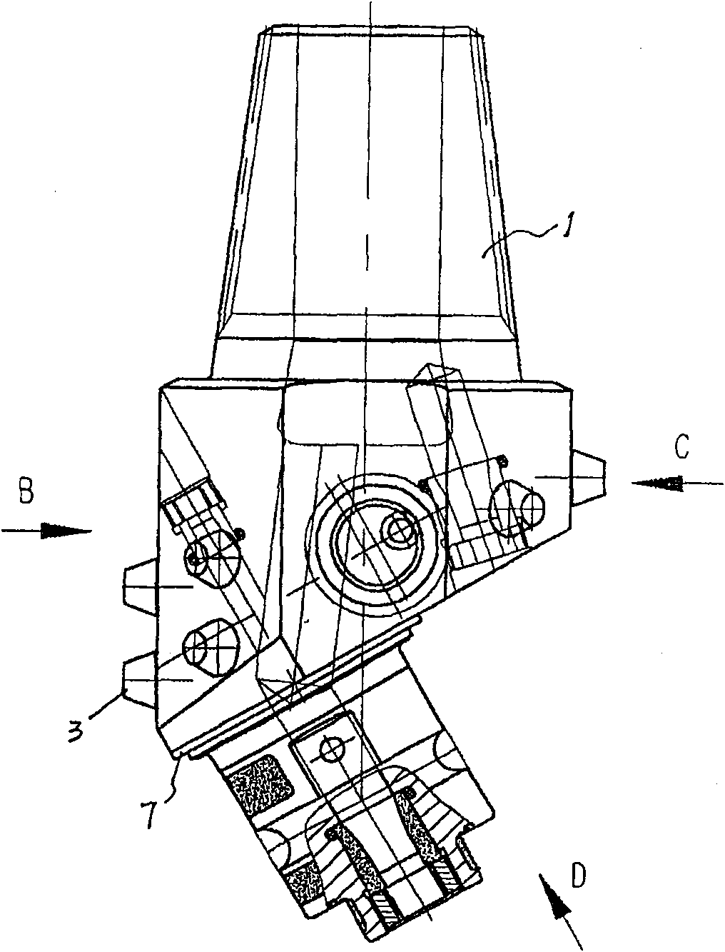
[0019] Such as Figure 1-6 The schematic diagram of the diameter-gauge structure of the single-cone drill bit of the present invention is shown in each direction. The cylindrical body of the claw 1 is divided into two asymmetric sections by the slope 4 of the claw. The cylinder is not long. Compared with the drill pipe, the ratio is extremely small and the diameter is maintained. Teeth 3 are made of alloy material, and one-third of the gauge teeth 3 are set on the upper end of the claw body's claw slope 4 highest point. In this example, three lower ends are provided with two-thirds of the gauge teeth 3. In this example Set 6 gauge teeth 3, that is, set 6 gauge teeth 3 at the lower part of the claw 1 anti-nozzle 2 outlet, the gauge teeth 3 are radially equiangularly symmetrical, distributed in an axially equidistant straight line, and radially adjacent to two teeth The axial spacing is less than or equal to the diameter of the addendum circle of the gage tooth 3, which is sligh...


PUM


Abstract

The invention discloses a track protecting structure for single roller bit. It contains pawl, reversed nozzle, track protecting gear, pawl sloping, roller face and roller etc. Two-thirds track protecting gears are arranged under the reversed nozzle of the pawl. The shortest distance between the exterior surface of track protecting gear which nearest to roller face and the lowest point under the pawl is larger than (or equals to) the largest diameter of the track protecting gear. The track protecting gear is symmetrical in radial and distributes equally and linearly in axial, which guarantees small quantity of overlap in cutting trace. The above structure can shorten the flow field at bottom of well, which brings smooth sidewall and safe drilling.

Description

Technical field: [0001] The invention relates to a diameter-gauge structure of a roller-cone bit, in particular to a diameter-gage structure of a single-cone bit. Background technique: [0002] At present, the single cone bit used in petroleum, mining and geological drilling, when drilling, due to the rotation of the cone and the revolution around the centerline of the drill bit, the carbide teeth of the drill bit will cut the bottom of the well in a mesh shape, and at the same time form an arc. Inclined groove-shaped rough well wall, this kind of rough well wall reduces the effective section of the wellbore and threatens the safety of the drill bit. The deeper the well, the stricter the safety requirements for drilling. Therefore, there is no single tooth drill bit with gauge structure. The quality of the borehole is not high, the practical value is low, and the safety performance is poor. However, the existing single-cone bit gauge structure such as "a single-cone bit" in ...

Claims


Application Information

Patent Timeline
Patent Type & Authority Patents(China)
IPC IPC(8): E21B10/08E21B10/16E21B10/18
Inventor 易楠辉涂小芳徐延金
Owner 江西飞龙钻头制造有限公司
Learn More