
Method and device for realizing automatic gain control

A technology of automatic gain control and feedback control, applied in gain control, amplification control, electrical components, etc., can solve the problems of low accuracy of observable estimated values, inability to update weights, and low accuracy

Inactive Publication Date: 2010-02-24
HUAWEI TECH CO LTD +1
View PDF2 Cites 0 Cited by
  • Summary
  • Abstract
  • Description
  • Claims
  • Application Information

AI Technical Summary

Problems solved by technology

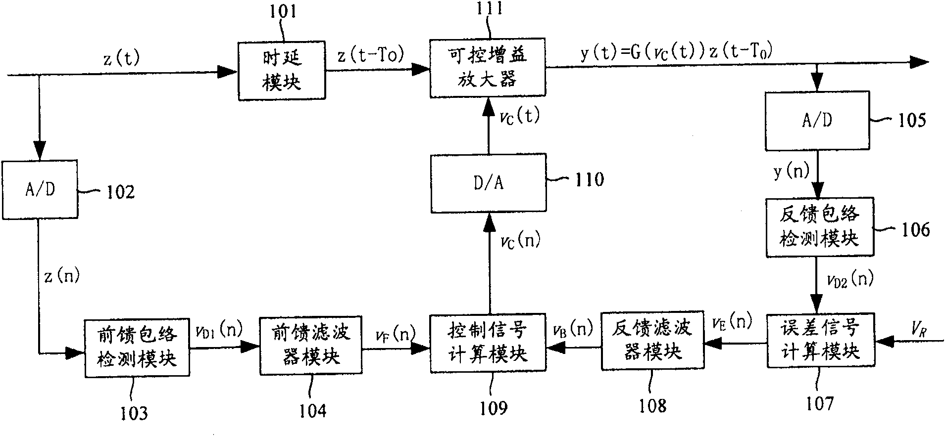
[0018] It can be seen from the above implementation process that in the existing feed-forward-feedback hybrid automatic gain control, whether it is an observable envelope estimate or an observable energy estimate, the calculation process uses a linear function method to calculate, that is to say, the weight of each instantaneous observation is the same, because the calculation method cannot update the weight according to the signal characteristics, so the accuracy of the observable estimate is low
In addition, in the existing feed-forward-feedback hybrid automatic gain control, the control signal calculation module is only a simple adder, which calculates the total gain control signal v C (n) is also less accurate

Method used


Image

  • Method and device for realizing automatic gain control
  • Method and device for realizing automatic gain control
  • Method and device for realizing automatic gain control

Examples


Embodiment Construction

[0093] The present invention will be described in further detail below in conjunction with the accompanying drawings.

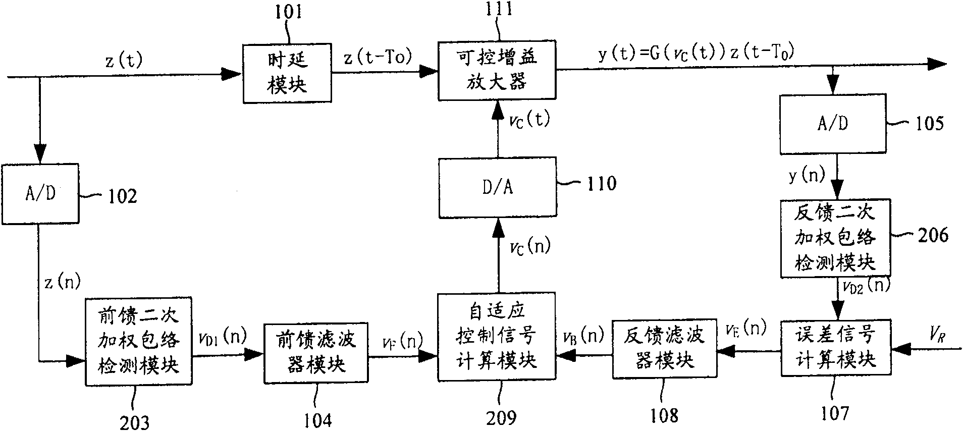
[0094] The train of thought of the present invention is: apply the quadratic function fitting method to obtain the observable estimated value, apply the minimum mean square error method to calculate the total gain control signal, thereby improving the accuracy of the observable estimated value and the total gain control signal performance, thereby improving the overall performance of the system.

[0095] figure 2 Shown is a schematic diagram of the basic structure of the circuit implementing the feed-forward-feedback hybrid automatic gain control applied in the present invention. In this embodiment, an observable estimated envelope value is taken as an example for specific description.

[0096] The input signal z(t) is delayed by T through the Delay module 101 0 The delayed input signal z(t-T 0 ); the input signal z (t) is sent to the feedforward quadrat...


PUM


Abstract

The invention provides a method for reaching auto-gain control and its device. The method comprises that using the method of quadratic function matching to attain the observable estimated value and using the method of least mean square error to calculate the total gain control signal; the device mainly supplies a quadratic weighted detecting module which can attain the observable estimated value by the method of quadratic function matching and a self-adaptive control signal calculate module which can calculate the total gain control signal by the method of least mean square error. The invention increases the accuracy of attained observable estimated value and the total gain control signal, to improve the properties of catching time, traceability, and the signal-to-noise ratio of said system, therefore, the whole property of system is improved.

Description

technical field [0001] The invention relates to the technical field of automatic gain control, in particular to a method and device for realizing automatic gain control. Background technique [0002] In the mobile communication system, the harsh wireless propagation environment makes the dynamic variation range of the received signal very large, up to about 80dB. The large-scale change of the received signal will bring many difficulties to the system design. Therefore, in the receiver of the communication system, the automatic gain control technology is generally used to adjust the signal with a large dynamic range to a signal with a small dynamic range. . Automatic Gain Control (AGC, Automatic Gain Control) can be implemented in many ways. From the perspective of circuit, analog circuit or digital circuit can be used. From the perspective of feedback type, feedback AGC and feedforward AGC can be used. From the perspective of implementation location, it can be implemented ...

Claims


Application Information

Patent Timeline
Patent Type & Authority Patents(China)
IPC IPC(8): H03G3/20H03G3/28H04B1/06
Inventor 陆文凯王斌杨勇冯淑兰刘华斌
Owner HUAWEI TECH CO LTD
Learn More