
Catheter tube for medical treatment and method of manufacturing the same

A medical and catheter technology, applied in the field of medical catheters, can solve the problems such as gradual control of insufficient rigidity and flexibility, metal braid flying out, setting the state of the catheter, etc., and achieves the effect of excellent position adjustment.

Inactive Publication Date: 2007-07-18
KANEKA CORP
View PDF6 Cites 34 Cited by
  • Summary
  • Abstract
  • Description
  • Claims
  • Application Information

AI Technical Summary

Problems solved by technology

[0017] However, it is very cumbersome to irradiate laser light with a wavelength of 1.06 μm and intermittently remove a part of the above-mentioned weave along its entire length direction.
And in the subsequent process, after the outer periphery of the catheter body made of thermoplastic resin inserted with the metal core wire is continuously covered to form a metal braid, the catheter body is heated and softened, and the braid is eaten into the outer surface by 1% of its thickness. / 2~1 / 5 and curing to form the torsion transmission part continuously, when the catheter body is softened by heating and eating into the braid, the warping of the cut end due to the elasticity of the metal braid will cause the metal braid to fly out on the surface of the catheter body, etc. problem, poor productivity
Moreover, the gradual control of stiffness and softness is not fully obtained
In addition, there is no idea of ​​​​setting the state of the catheter to correspond to various access paths

Method used


Image

  • Catheter tube for medical treatment and method of manufacturing the same
  • Catheter tube for medical treatment and method of manufacturing the same
  • Catheter tube for medical treatment and method of manufacturing the same

Examples


Embodiment Construction

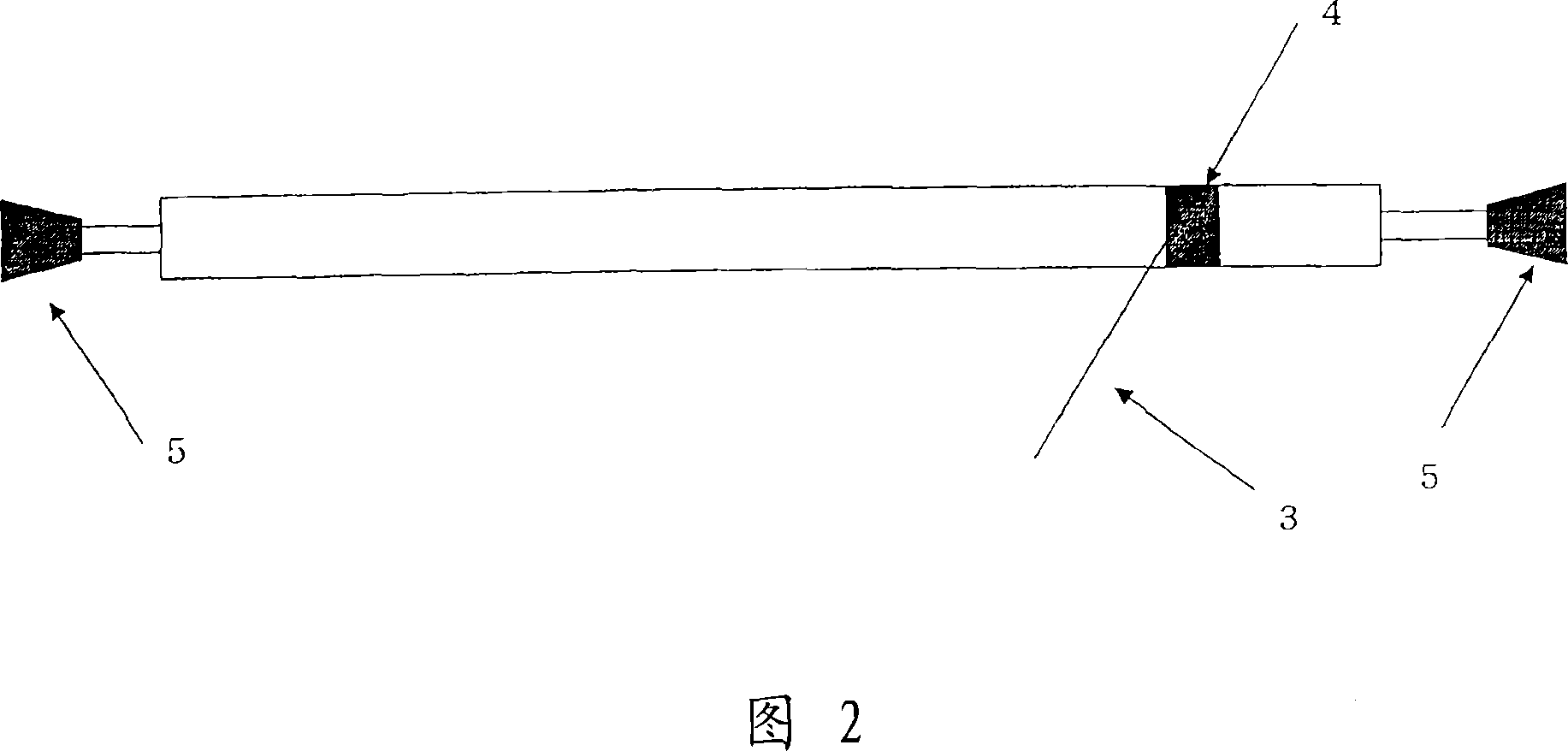
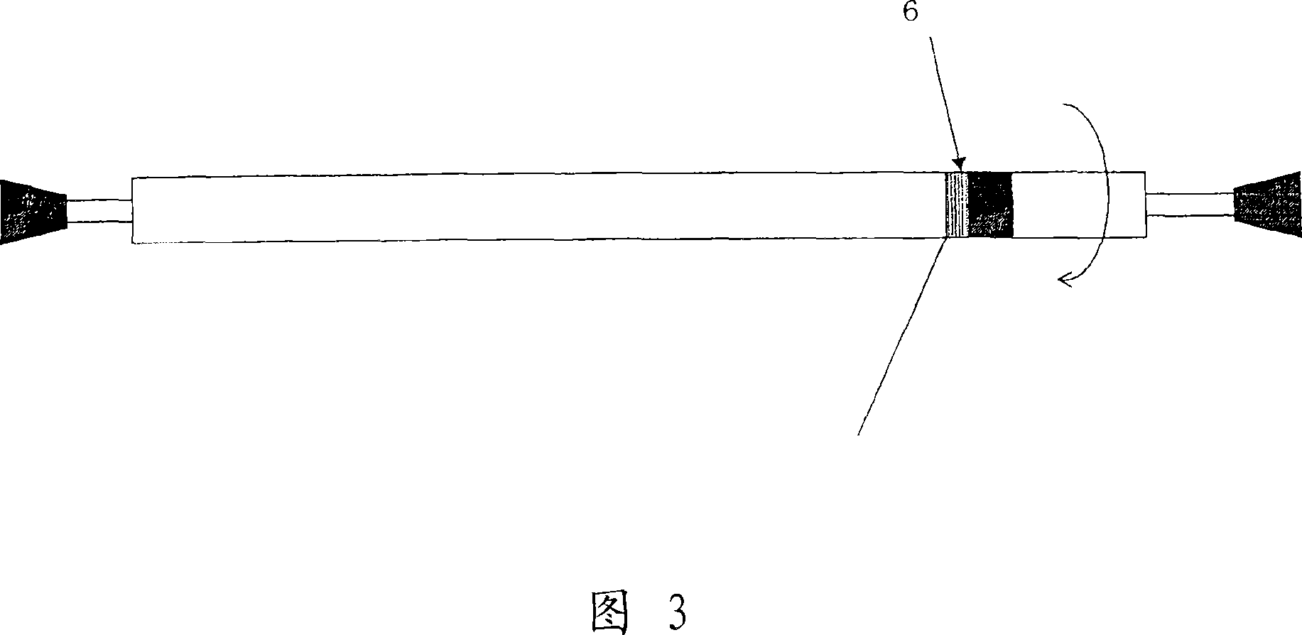
[0088] Next, the most preferable embodiment and manufacturing method of the medical catheter of the present invention will be described with reference to the drawings. These figures are diagrams schematically showing the structural features of the present invention, and the length and diameter of each part may be arbitrary as long as it is suitable as a medical catheter.

[0089] First, a duct in which the linear body constituting the reinforcing material layer is wound without being folded as the first aspect of the present invention will be described.

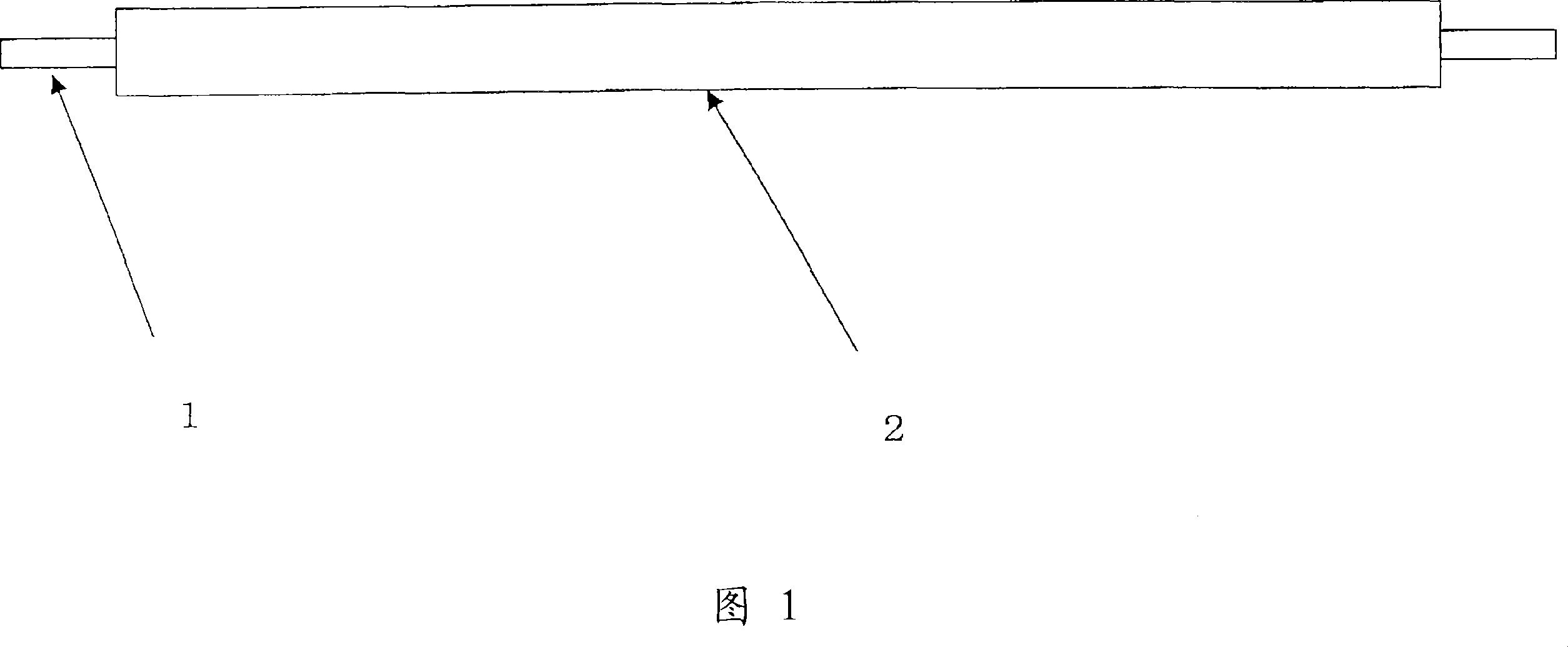
[0090] First, the inner layer tube 2 covering the metal core wire 1 as shown in FIG. 1 is prepared. In addition, in FIG. 1 , the left side is the root portion of the catheter (hereinafter referred to as the root portion), and the right side is the distal portion of the catheter (hereinafter referred to as the distal portion).

[0091] The constituent material of the inner layer tube is not particularly limited as long as it ...


PUM


Abstract

A catheter tube for medical treatment having a high degree of freedom in having its rigidity and flexibility changed stepwise and enabling the setting of a bending rigidity changing position according to a variety of access routes and a method of manufacturing the catheter tube. The catheter tube comprises an inner layer tube, a reinforcement material layer, a marker, and an outer layer tube which are formed integrally with each other. The catheter tube is so formed that a line body forming the reinforcement material layer is densely wound at its tip part, the marker formed of an X-ray impermeable metal wire adjacent to the tip thereof is also densely wound, and comprises a leading-edge part where the reinforcement material layer and the marker are not present. Accordingly, the bending rigidity of the catheter tube from the base part to ward the tip part is stepwise or continuously decreased by the presence of the reinforcement material layer and the outer layer tube. The winding of the line body is terminated at the base part after its interval and tilt angle are changed at positions between the densely wound portion of the tip part and a portion near the base part, and the outer layer tube has a stepwise-changing hardness arrangement. As a result, the catheter tube can be set to a variety of bending rigidity changing positions.

Description

technical field [0001] The present invention relates to a medical catheter having excellent position adjustment, torsion transmission, kink resistance, high degree of adjustment freedom of gradual control of stiffness and softness, and state setting properties corresponding to various access paths, etc. Manufacturing method. Furthermore, the present invention relates to a medical catheter capable of exhibiting moderate X-ray visibility and excellent flexibility at the distal end, and a method for manufacturing the same. Background technique [0002] A catheter is a cavity, tube, blood vessel, etc. that is inserted into the body. It is a hollow medical device used for injection of fluids such as selective angiographic contrast agents, suction of thrombus, access to blood vessels that are in an occluded state, and vasodilation, etc. , usually composed of a tube body. Such catheters are required to have excellent operability and to be able to be quickly and reliably inserted ...

Claims


Application Information

Patent Timeline
IPC IPC(8): A61M25/00
CPCA61M25/0053A61M25/0045A61M25/0108
Inventor 村田贵洋御林毅
Owner KANEKA CORP
Learn More