Electrophoresis painting dressing technical method for pipe fitting type metal, and metal piece with deep hole, and deep concave
A technology of electrophoretic coating and metal parts, applied in the direction of electrolytic coating, electrophoretic plating, coating, etc., can solve problems such as anti-corrosion, and achieve the effect of wide application range and simple process
- Summary
- Abstract
- Description
- Claims
- Application Information
AI Technical Summary
Problems solved by technology
Method used
Image

Examples
Embodiment 1
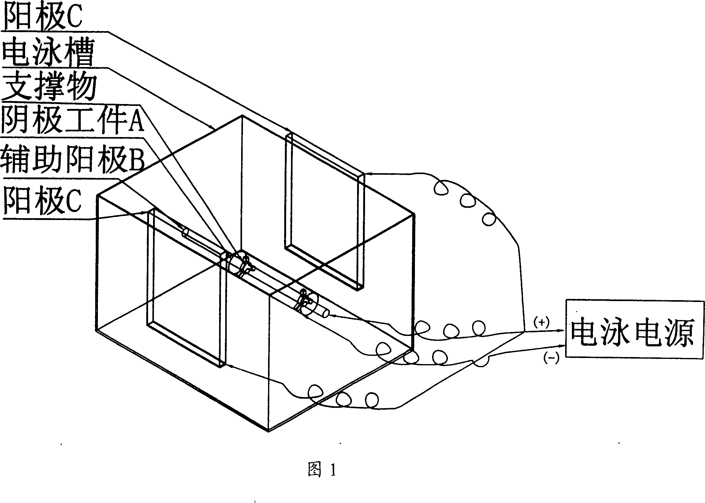
[0015] As shown in Figure 1, the concrete steps of the present invention are as follows:
[0016] 1. Connect the workpiece to the negative pole (-) of the power supply.
[0017] 2. Put the auxiliary anode into the workpiece.
[0018] 3. Connect the auxiliary anode to the positive pole (+) of the power supply, and connect the anode of the electrophoresis tank to the positive pole (+) of the power supply.
[0019] 4. Put the electrophoretic workpiece into the electrophoretic coating solution. Electrophoretic coating can choose polybutadiene resin, phenolic resin, epoxy resin, acrylic resin or polyurethane.
[0020] 5. Turn on the power. There are many methods: (1) Segmented electrophoresis can be used, and the anode and the auxiliary anode are connected and controlled by a switch. A. Electrophoresis the inside of the workpiece first, connect the switch to the auxiliary anode, and then electrophoresis the inside of the workpiece. After that, the power switch will be switched...
Embodiment 2
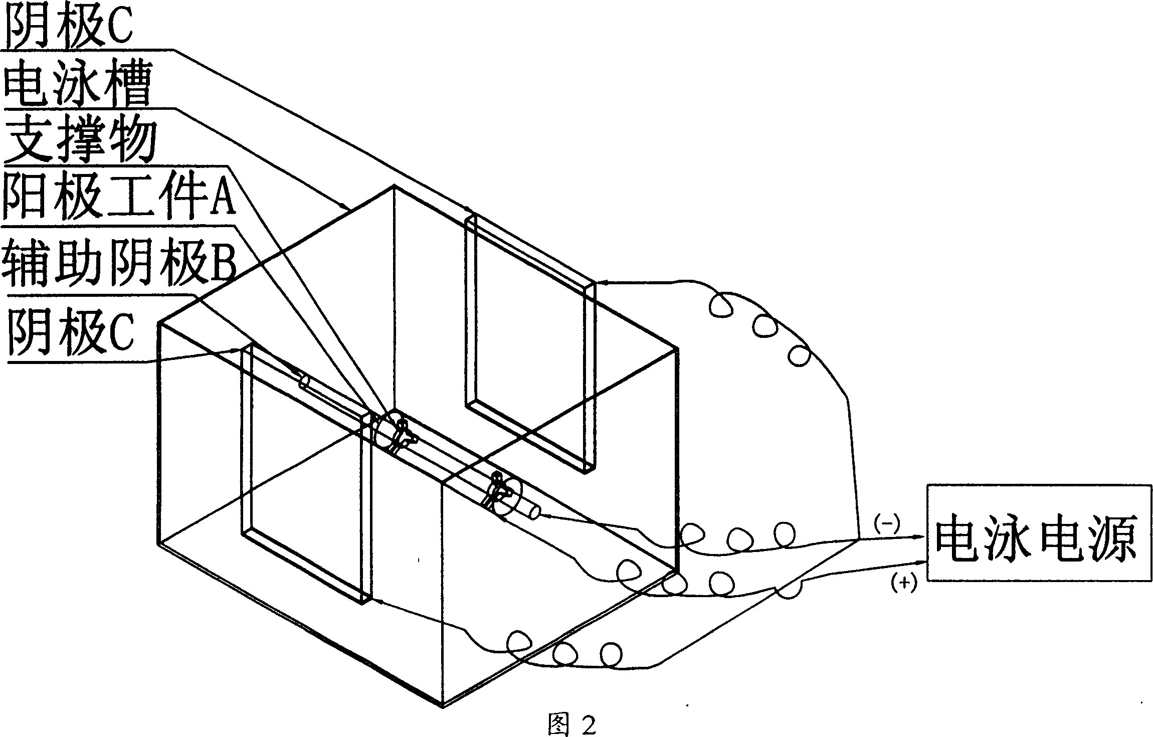
[0023] As shown in Figure 2, the concrete steps of the present invention are as follows:
[0024] 1. Connect the workpiece to the positive pole (+) of the power supply.
[0025] 2. Put the auxiliary cathode into the workpiece.
[0026] 3. Connect the auxiliary cathode to the negative pole (-) of the power supply, and connect the cathode of the electrophoresis tank to the negative pole (-) of the power supply.
[0027] 4. Put the electrophoretic workpiece into the electrophoretic coating solution. Electrophoretic coating can choose polybutadiene resin, phenolic resin, epoxy resin, acrylic resin or polyurethane.
[0028] 5. Turn on the power. There are many methods: (1) Segmented electrophoresis can be used, and the cathode and the auxiliary cathode are connected with a switch for control. A. First, the inside of the workpiece is electrophoresed, and the switch is connected to the auxiliary cathode, and then the inside of the workpiece is electrophoresed. After that, switch ...
Embodiment 3
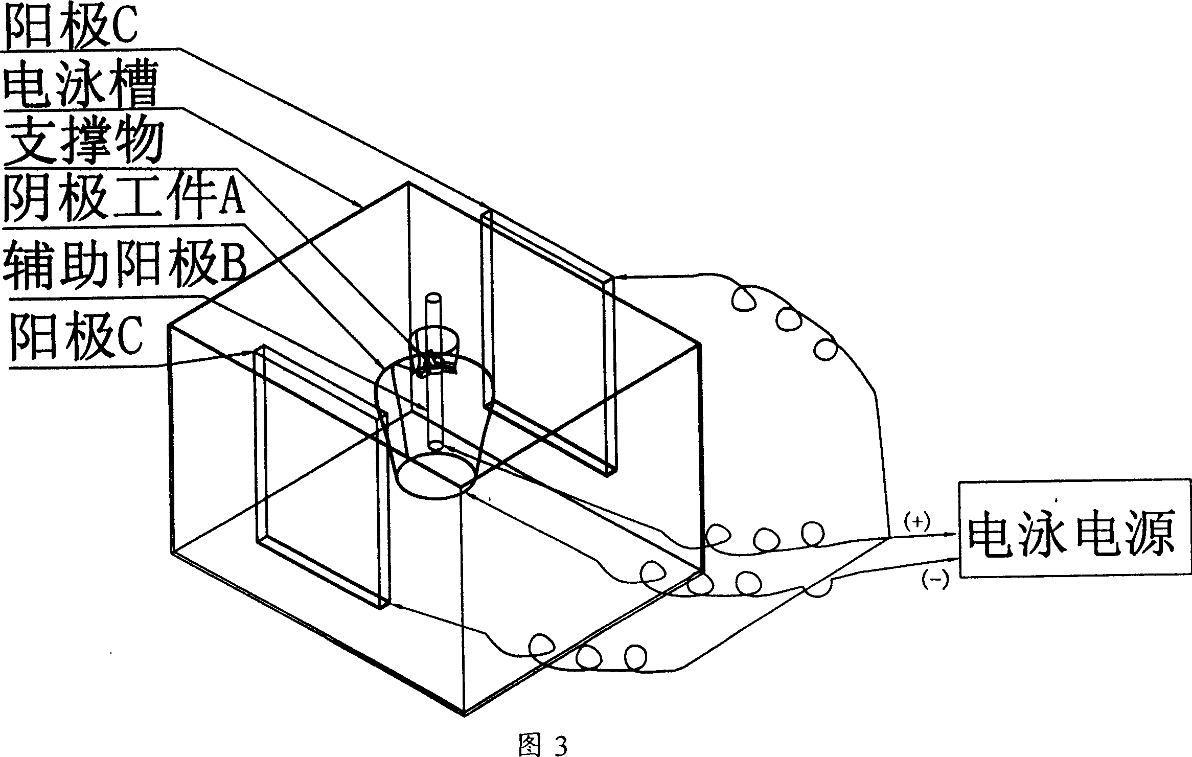
[0030] Embodiment 3 when cathodic electrophoresis process:
[0031] As shown in Figure 3, the workpiece (A) is the piece to be electrophoresed, connected to the negative pole (-) of the electrophoresis source, and the anode C is connected to the positive pole (+) of the power supply. At the same time, an auxiliary anode ( B). The auxiliary anode material is metal or non-metallic metallized conductor, which can pass current. The distance between the auxiliary anode and the inner pipe wall of the deep hole and the deep concave part can be far or close, but it cannot be in direct contact with the workpiece (A). It is necessary to use non-conductive non-conductive objects such as plastic, rubber, wood and other non-conductive bodies to support or block the auxiliary anode from touching and contacting the workpiece. At the same time, the non-conductive body has regular or irregular holes. It is beneficial for the electrophoretic coating to enter the interior of the workpiece. Th...
PUM
 Abstract
Description
Claims
Application Information
 - R&D
- Intellectual Property
- Life Sciences
- Materials
- Tech Scout
- Unparalleled Data Quality
- Higher Quality Content
- 60% Fewer Hallucinations
Browse by: Latest US Patents, China's latest patents, Technical Efficacy Thesaurus, Application Domain, Technology Topic, Popular Technical Reports.
© 2025 PatSnap. All rights reserved.Legal|Privacy policy|Modern Slavery Act Transparency Statement|Sitemap|About US| Contact US: help@patsnap.com