Rolling piston type compressor with no reservoir
A rolling piston type and compressor technology, which is applied in the direction of rotary piston type machinery, compressors, irreversible cycle compressors, etc., can solve the problems of shortening the life of the motor, taking up a large space for the compressor, and high exhaust temperature, so as to reduce production cost, reduced footprint, guaranteed reliability and high efficiency
- Summary
- Abstract
- Description
- Claims
- Application Information
AI Technical Summary
Problems solved by technology
Method used
Image

Examples
Embodiment 1
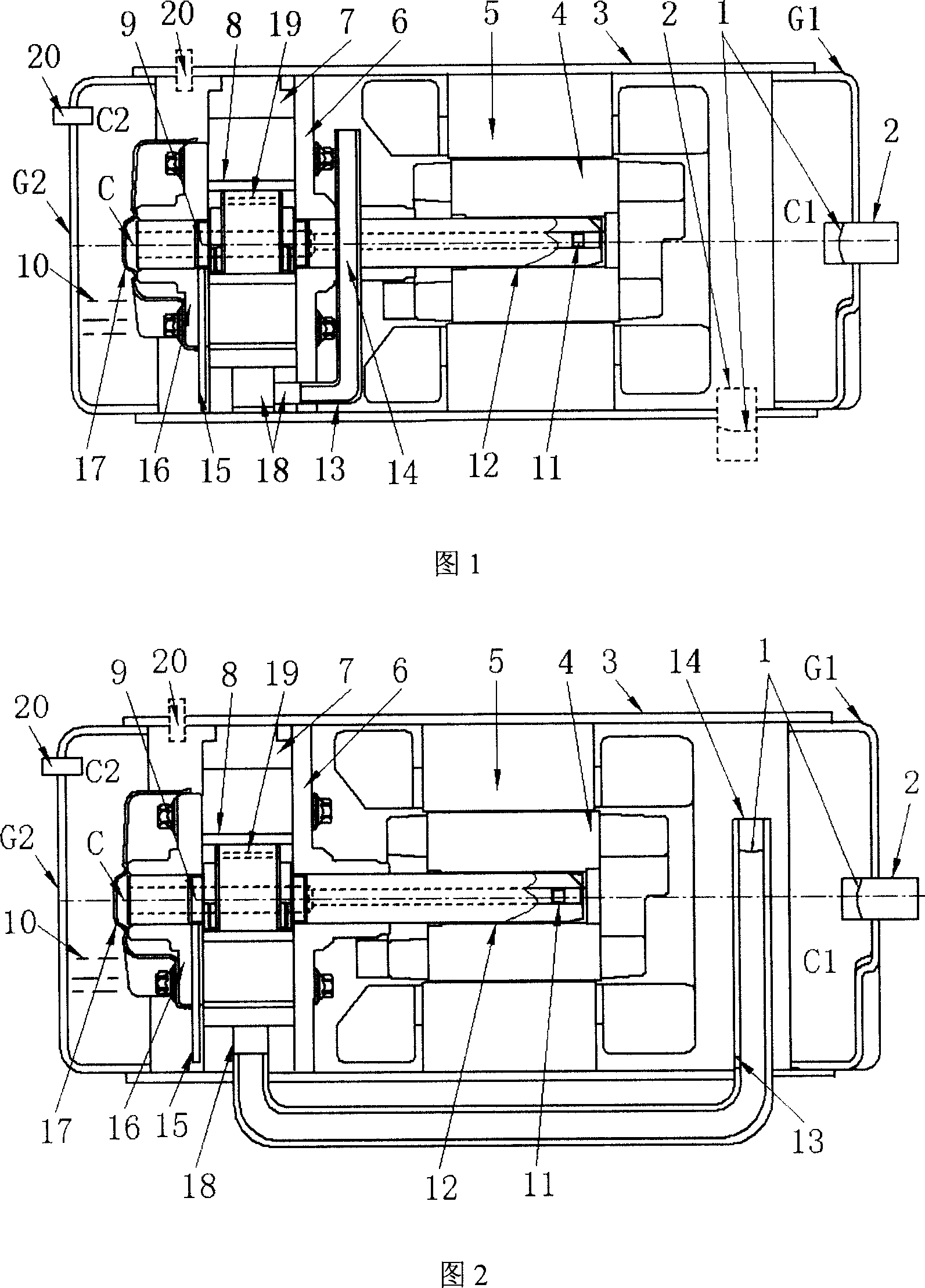
[0027] Example 1: A single-cylinder horizontal compressor built into the suction pipe (as shown in Figure 1)
[0028] The two ends of the horizontally arranged casing 3 are sealed by the casing covers G1 and G2, and the interior is divided into two parts by the main bearing 6 (or cylinder 7 or other partitions), that is, the low-pressure chamber C1 under the suction pressure during operation and the low-pressure chamber C1 under the discharge pressure. The high-pressure chamber C2 of air pressure, the motor part composed of the rotor 4 and the stator 5 is arranged in the chamber C1, and the compression pump part composed of the cylinder 7, the crankshaft 12, the piston 8 and the main and auxiliary bearings 6, 16 is accommodated in the chamber C2 , the inner bottom of which is a lubricating oil pool 10, and the housing 3 is provided with an intake pipe 2 and an exhaust pipe 20 communicating with the system. The intake pipe 2 with the filter screen 1 is installed on the shell co...
Embodiment 2
[0029] Example 2: A single-cylinder horizontal compressor with an external suction pipe
[0030] The suction pipe 14 is placed outside, and the oil return hole 13 is opened at the position of the suction pipe 14 close to the bottom of the housing 1. The other structures are the same as those in the first embodiment, as shown in FIG. 2 .
Embodiment 3
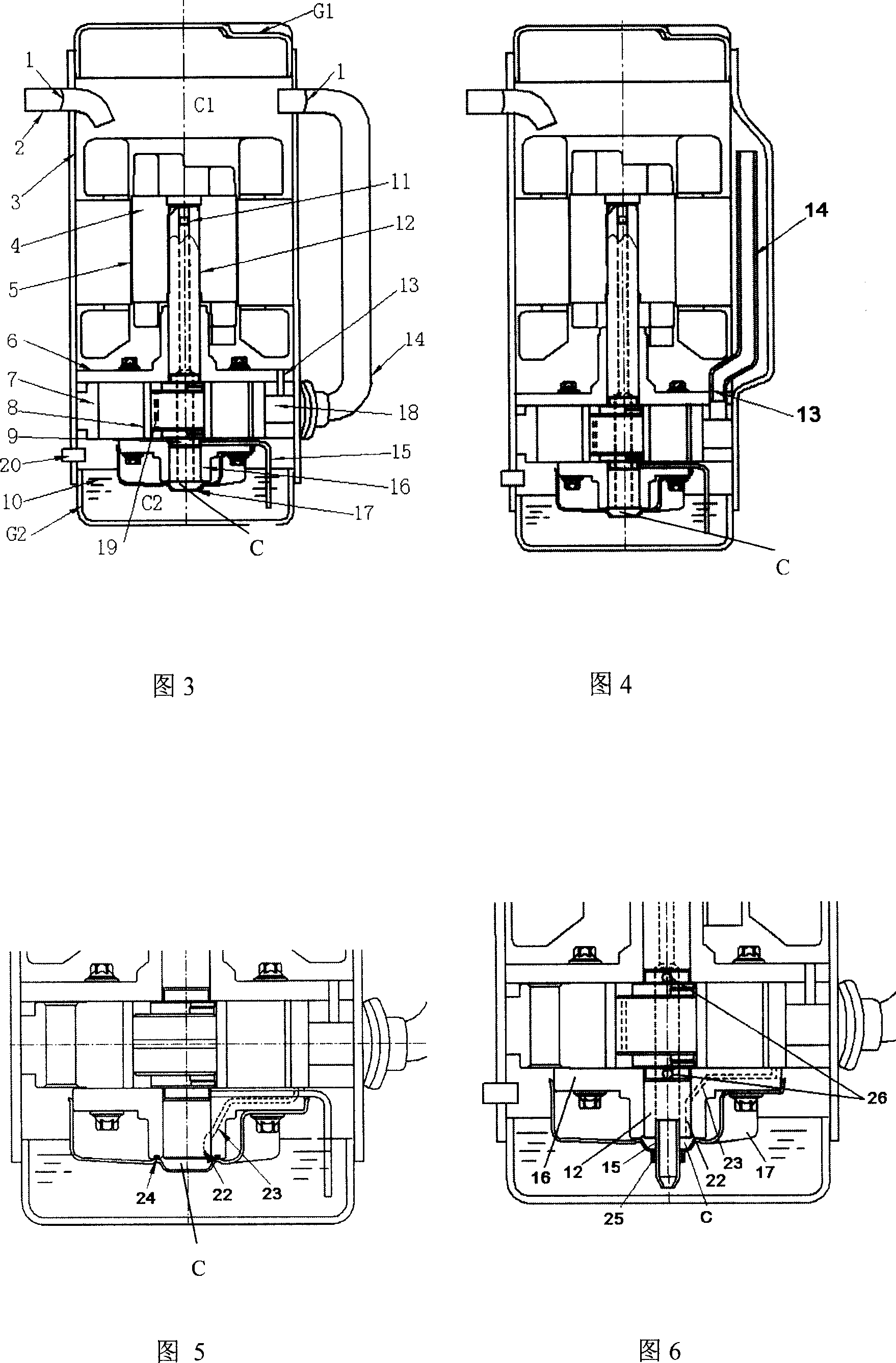
[0031] Example 3: A single-cylinder vertical compressor with an external suction pipe
[0032] The two ends of the vertically arranged housing 3 are sealed by the housing covers G1 and G2, and the interior is divided into two parts by the partition main bearing 6, namely the low-pressure chamber C1 and the high-pressure chamber C2, which are in a vertical structure. Chamber C1 houses the motor, chamber C2 houses the compression pump part, oil sump 10 . The intake pipe 2 is arranged on the upper side of the casing 3 , and the exhaust pipe 20 is arranged on the lower side of the casing 3 . The suction pipe 14 is vertically arranged outside the casing, the upper end communicates with the chamber C1 , and the lower end communicates with the suction port 18 . The oil return hole 13 is arranged on the separator main bearing 6 and communicates with the suction port 18 on the cylinder 7 . As shown in Figure 3.
PUM
 Abstract
Description
Claims
Application Information
PatSnap Eureka turns technology decisions into work you can execute. Powered by our Innovation Knowledge Graph, it runs expert workflows across engineering, life sciences, materials and intellectual property. Get your review-ready output in minutes.


