Ankle joint rehabilitation training device

A technology for rehabilitation training and ankle joint, applied in the field of medical devices, can solve the problems of complex control system, poor processing and manufacturing, difficult to popularize and apply, etc., and achieve the effects of simple mechanical system structure, good manufacturing and processing performance, and simplified control system design

Inactive Publication Date: 2007-08-01
SICHUAN UNIV
View PDF0 Cites 61 Cited by
  • Summary
  • Abstract
  • Description
  • Claims
  • Application Information

AI Technical Summary

Problems solved by technology

For example, the Rutgers Ankle system uses a Stewart mechanism with six degrees of freedom, the control system is complicated, the cost is high, and it is difficult to

Method used


Image

  • Ankle joint rehabilitation training device
  • Ankle joint rehabilitation training device
  • Ankle joint rehabilitation training device

Examples


Embodiment 1

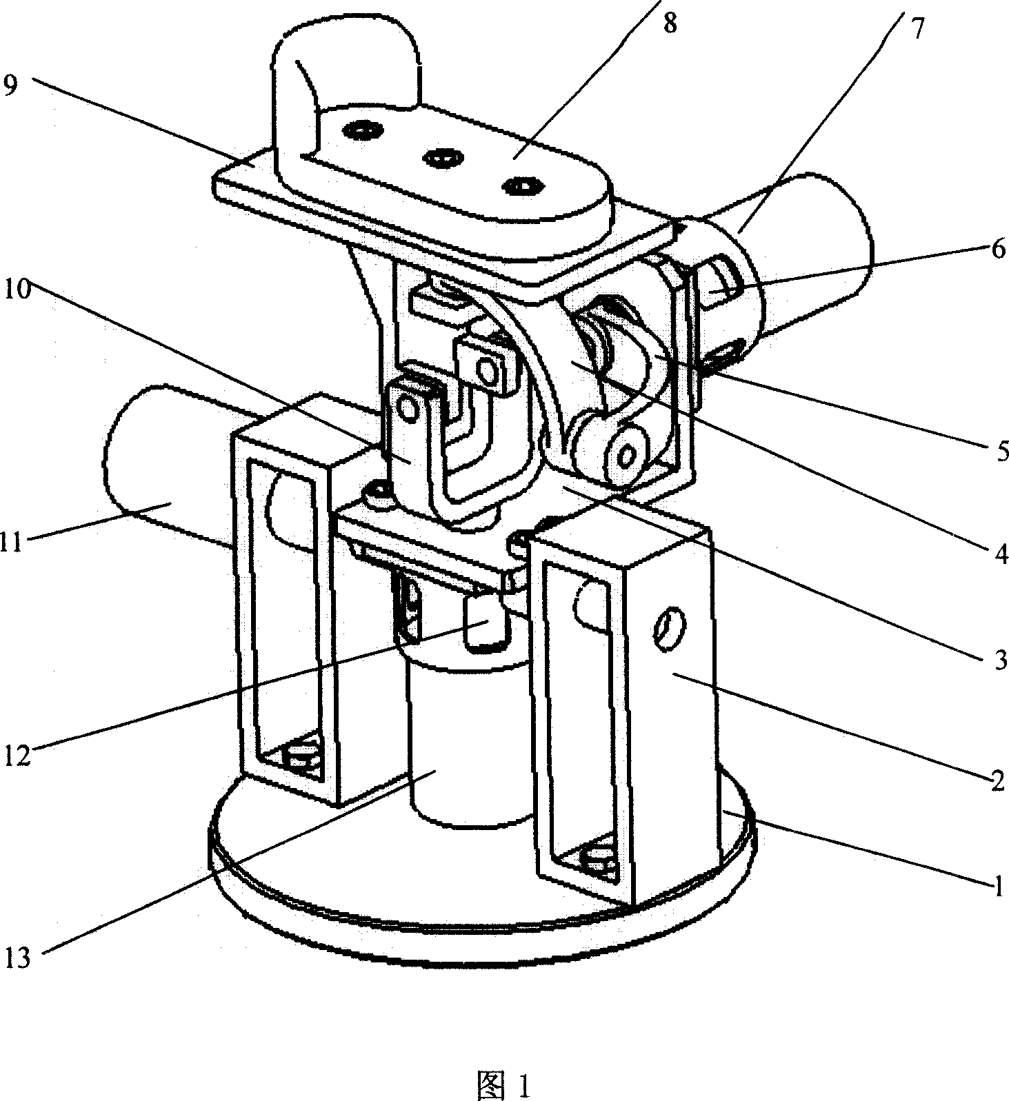
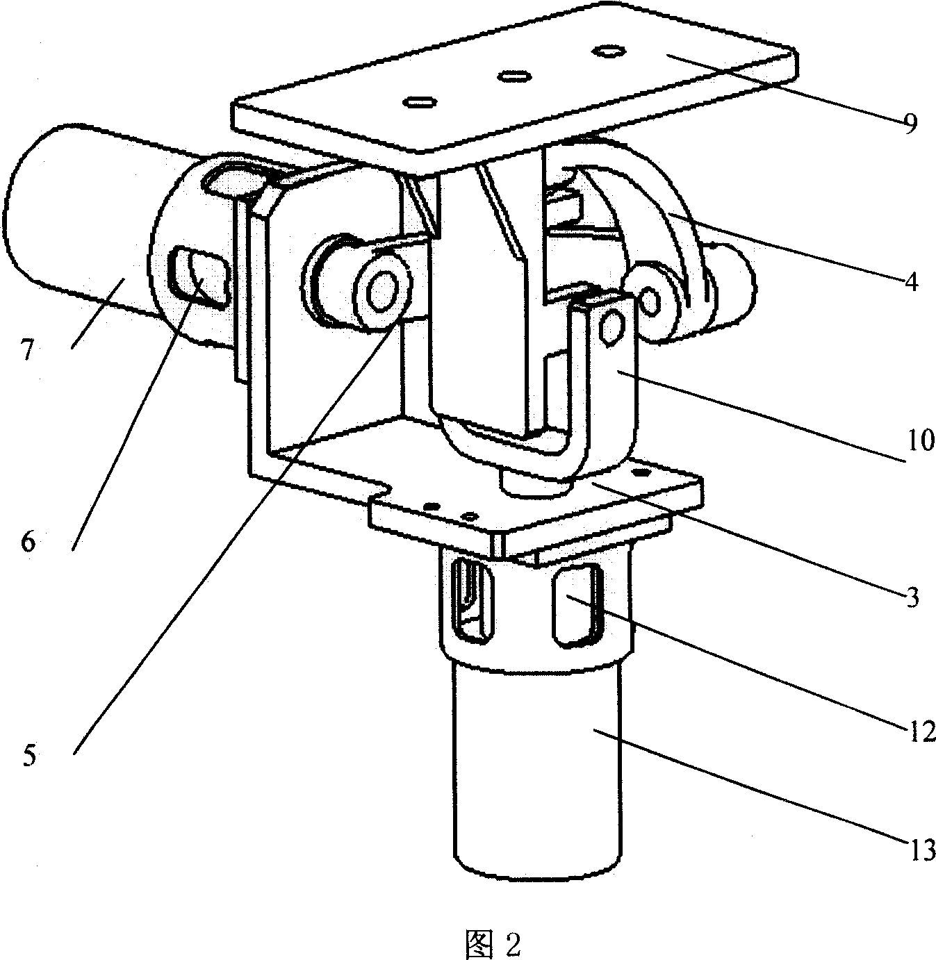
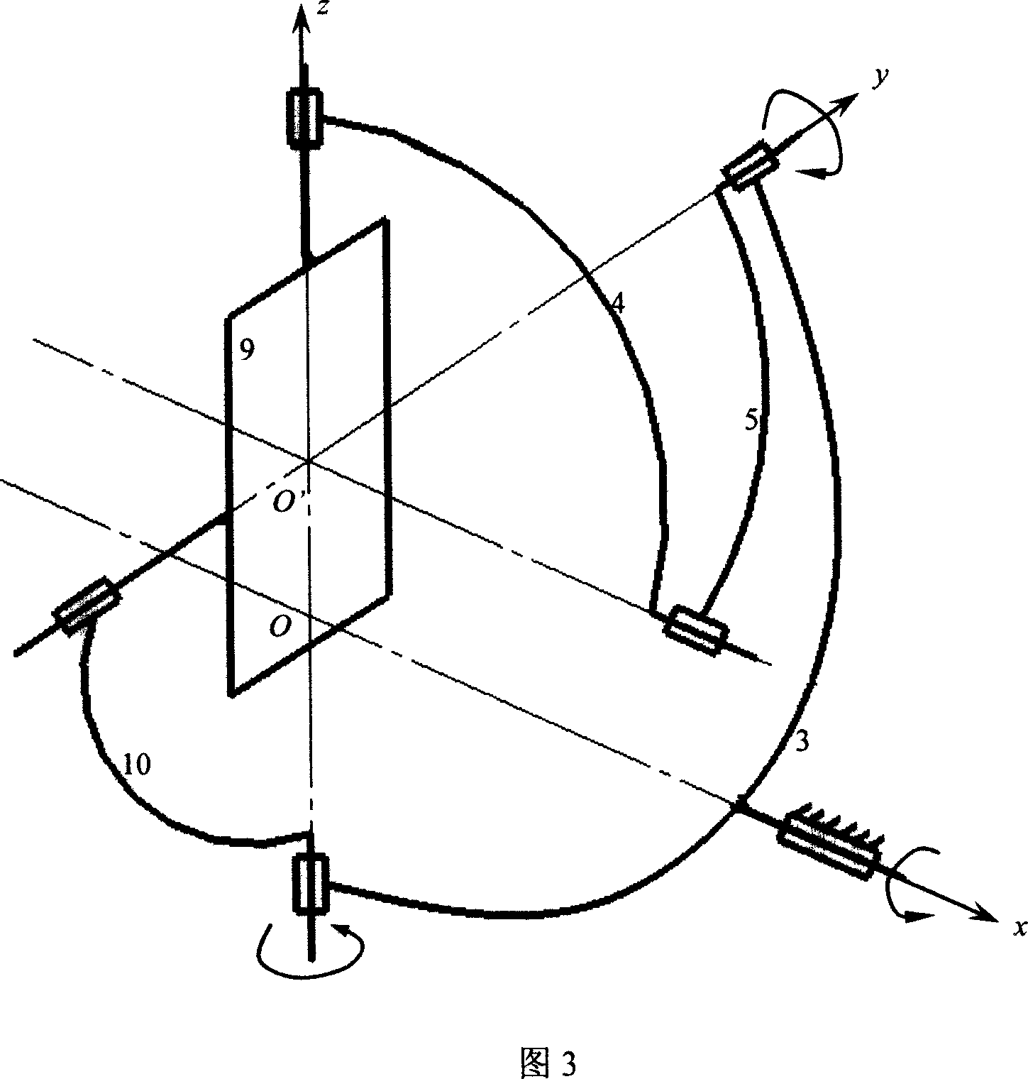
[0023] The structure of the ankle joint rehabilitation training device of this embodiment is shown in FIG. 1 , accompanying drawing 2 and accompanying drawing 3 . It consists of a rotating mechanism with one degree of freedom, a spherical parallel mechanism with two degrees of freedom, and a tray 8. The spherical parallel mechanism is composed of a fixed platform 3, a moving platform 9 as an output component, and 3 connecting rods, one of which is 10 is a "Y"-shaped structural rod, which is connected with the fixed platform and the moving platform through a rotating pair to form a movement branch chain that drives the movement of the movement platform. The movement branch chain is driven by a servo motor 13 through a coupling 12, and the movement platform Driven by the motion branch chain, it rotates around the Y axis. The other two connecting rods 4 and 5 are connected to each other through a rotating pair, wherein the other end of the connecting rod 5 is connected with the s...

Embodiment 2

[0026] The structure of the ankle joint rehabilitation training device of this embodiment is shown in Fig. 4, Fig. 5 and Fig. 6 . The structure of the ankle joint rehabilitation training device of this embodiment is basically the same as that of Embodiment 1, the only difference is that the 2-DOF spherical parallel mechanism mounted on the frame support 2 through the rotating pair is driven by the servo drive motor 11 The X-axis of the rotation axis intersects at the intersection of the two rotation axes of the moving platform - the Y-axis and the Z-axis. Its schematic diagram is shown in Figure 6.

Embodiment 3

[0028] The structure of the ankle joint rehabilitation training device of this embodiment is shown in Fig. 7 , Fig. 8 and Fig. 9 . The structure of the ankle joint rehabilitation training device of this embodiment is basically the same as that of Embodiment 1, the difference is that the two servo motors driving the two parallel branch chains are respectively installed on the two mounting supports of the fixed platform, and the spherical surfaces are connected in parallel. The moving platform of the mechanism output member is driven by two parallel motion branch chains composed of three connecting rods. The two rotation axes of the rotary motion are the X axis and the Y axis, as shown in Figure 8. Through the 2-degree-of-freedom spherical parallel mechanism that the rotating pair is installed on the frame of the rotating mechanism, the axis of the rotary motion driven by the servo drive motor 11 is the Z axis, and the Z axis intersects the intersection of the X axis and the Y ax...


PUM


Abstract

The invention discloses an ankle-joint exercising device based on paralleling mechanism, which comprises the following parts: rotary mechanism with one free degree, spherical paralleling mechanism with two free degrees and tray, wherein the spherical paralleling mechanism is composed of mobile platform to fix tray, two branched chains and fixed platform, which connect each other through driving spoke; the fixed platform of spherical paralleling mechanism connects rotary component of rotary mechanism rigidly, which is set on the rack bearing of rotary mechanism through driving spoke to form 3 free degrees; the tray is assembled on the mobile platform of spherical paralleling mechanism.

Description

1. Technical field [0001] The invention belongs to the field of medical devices, and relates to a rehabilitation training device, in particular to a device for ankle sprain and orthopedic rehabilitation training. 2. Background technology [0002] Ankle joint injury is a common bone and joint injury, and its incidence rate ranks second among lower extremity injuries. The clinical treatment of ankle joint injuries proves that functional rehabilitation training for ankle joints during the rehabilitation period can accelerate tissue healing and help restore the proprioception of ligaments, speed up the recovery of patients, and prevent repeated sprains caused by ankle joint instability in the future . Existing ankle joint rehabilitation training devices usually only have one or two degrees of freedom, which cannot truly simulate the complex movement of the ankle joint. Rutgers University in New Jersey, USA developed a Rutgers Ankle ankle joint rehabilitation system in 1999, wh...

Claims


Application Information

Patent Timeline
IPC IPC(8): A61H1/00A63B23/08
Inventor 徐礼钜张均富徐雪梅李翔龙
Owner SICHUAN UNIV
Why Eureka
Try Eureka