Dry slag-draining device of coal boiler

A technology for dry slag removal and coal-fired boilers, applied in lighting and heating equipment, etc., can solve the problems of heat loss of combustible substances, coking of bottom slag, over temperature of conveyor belt box, etc., and achieve the effect of improving the cooling effect of slag

Inactive Publication Date: 2007-08-01
BEIJING GUODIAN FUTONG SCI & TECH DEV
View PDF5 Cites 44 Cited by
  • Summary
  • Abstract
  • Description
  • Claims
  • Application Information

AI Technical Summary

Problems solved by technology

[0002] At present, coal-fired boilers in power stations mainly use hydraulic slag removal systems and equipment, but this system and equipment have the following disadvantages: (1) The slag falls directly into the cooling water from the bottom of the boiler, so that the combustible substances and heat contained in the ash The water vapor generated at the same time will corrode the bottom parts of the boiler; (2) the consumption of water resources is large, and the discharge of ash and slag water will also cause environmental pollution, and the treatment cost is high; (3) the system is complicated and the maintenance cost is high
And this patent also has the following deficiencies: (1) when the bottom of the boiler combustion chamber is opened so that the bottom slag is discharged and falls to the conveyor belt, since the boiler combustion chamber is in a vacuum state, the external ambient air is under atmospheric pressure. Under the action, it enters the furnace through the suction port, and the amount of air entering the furnace cannot be controlled
(2) The supporting plate of the conveyor belt is designed in a grid shape, and the function is to let the air flow through the slag layer. However, when the amount of slag is large in this structure, the slag layer on the supporting plate will accumulate very thickly, and it is difficult for the air to pass through the slag layer to achieve cooling. So cooling is less efficient
This technology has the following disadvantages: (1) The boiler is affected by coal quality or combustion state, and the bottom slag will coke
If hundreds of kilograms of slag appears, it will directly impact the conveyor belt from the combustion chamber, causing damage to the conveyor belt components
(2) When the amount of slag discharged from the boiler is large, due to insufficient cooling of the slag, the temperature of the outer cover and box of the conveyor belt will often exceed the specified temperature, which will affect the safety of production
However, since the cooling air absorbs heat and all enters the furnace, if the amount of air entering the bottom of the boiler (theoretically defined as air leakage) exceeds the allowable value (boiler air excess coefficient), it will affect the normal combustion of the boiler, thus reducing the efficiency of the boiler
(4) When the amount of slag discharged from the boiler is large, in order to meet the slag cooling effect, it is necessary to extend the length of the high-temperature conveyor belt or increase the number of conveyor belts, which increases the cost
This patent has following deficiencies: (1) adopts two conveyer belts to carry out continuous cooling, has increased production cost
(2) When the boiler encounters a large amount of bottom slag or coking caused by coal quality changes, the required amount of cooling air will increase, but since the cooling air absorbs heat, it will all enter the furnace, and the amount entering the furnace exceeds the allowable amount of the boiler. Excessive cooling air will increase the loss of exhaust gas and affect the normal operation of the boiler
(3) It is difficult for the double-open movable door to withstand the huge impact force of the large slag, and it cannot effectively control the size of the intercepted slag

Method used


Image

  • Dry slag-draining device of coal boiler
  • Dry slag-draining device of coal boiler
  • Dry slag-draining device of coal boiler

Examples


Embodiment Construction

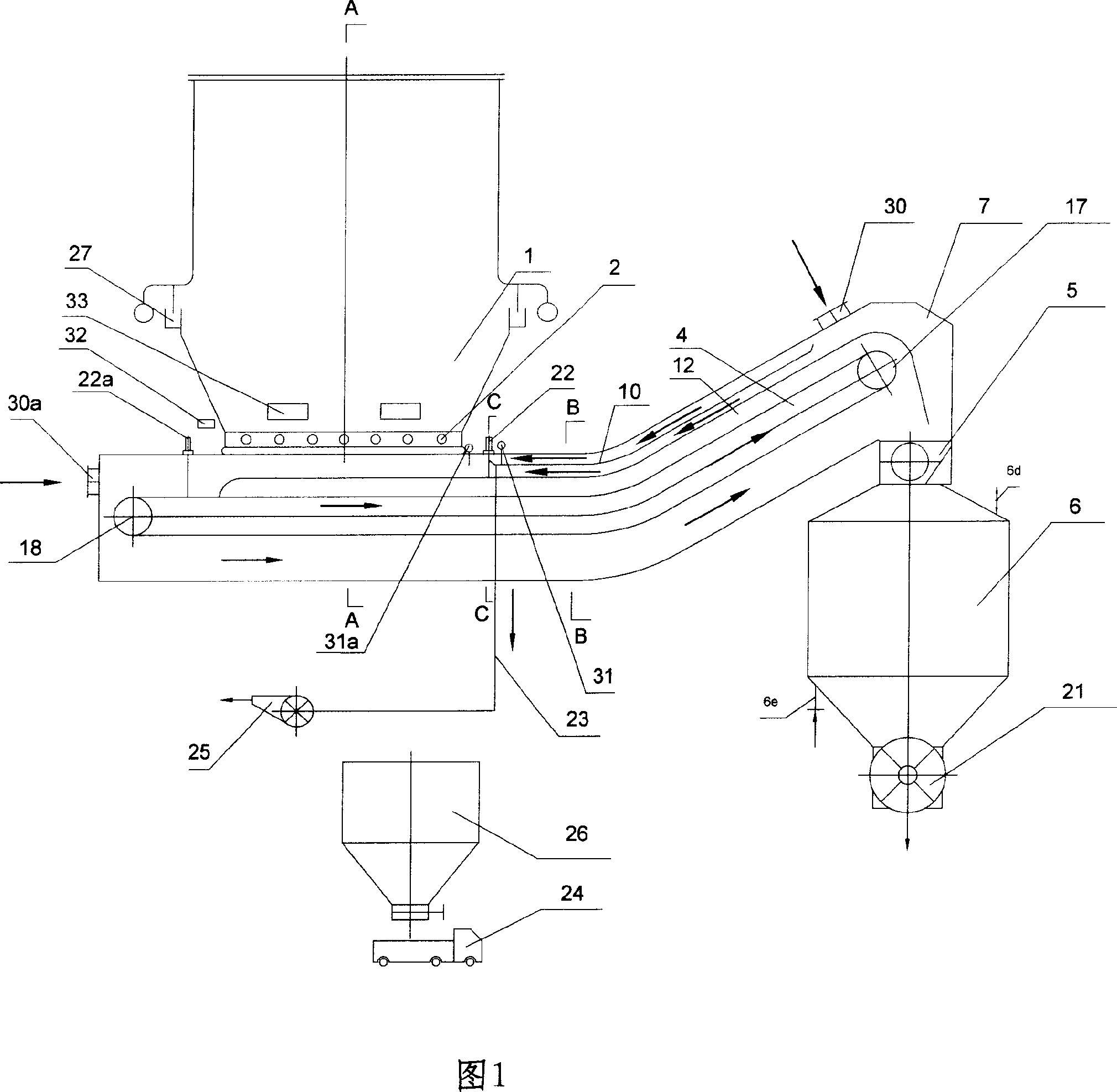
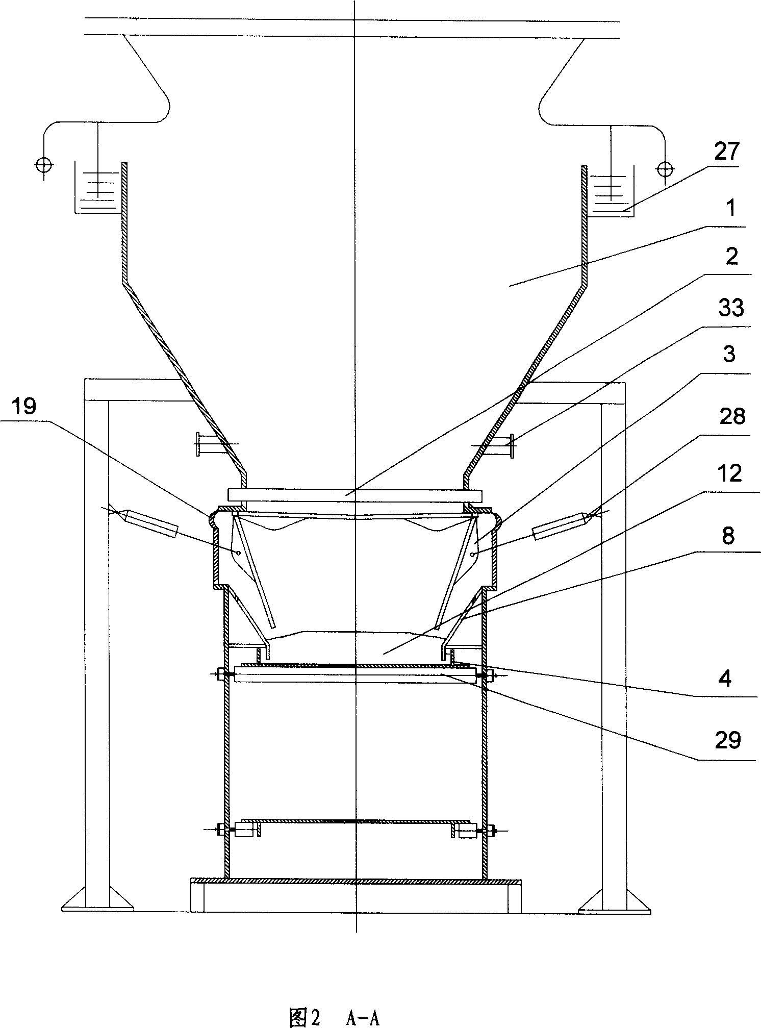
[0024] Referring to Fig. 1 to Fig. 5, the boiler slag storage hopper 1 of the dry slagging device of the present invention is connected with the combustion chamber of the boiler through a water seal groove 27 (a high temperature resistant metal expander can also be used), and the water seal groove 27 is mainly used for absorbing The high-temperature thermal expansion of the boiler body in the X, Y, and Z (three-dimensional) directions, and the boiler slag storage hopper 1 is supported by a steel structure.

[0025]Under the boiler slag storage hopper 1, a number of grids 2 made of high-temperature-resistant and impact-resistant materials are evenly distributed. The grids 2 are also supported by the steel structure of the boiler slag storage hopper 1. The distance between the grids 2 is generally designed according to the coking condition of the boiler. 300-1000mm. The high-temperature furnace bottom slag falling from the combustion chamber of the boiler has a temperature of ab...


PUM


Abstract

The invention discloses a coal boiler dry-type slag discharger, which comprises a seal box sealed and connected with the slag hopper of boiler. The seal box contains a high-temperature resistant transmission band; the descending part along the direction of transmission band between the seal box and the slag hopper is arranged with a wind inlet; the seal box is arranged with a wind valve for limiting the inlet cooling air into the slag hopper, while the wind valve is between the connection of seal box and slag hopper and the wind inlet; the seal box is also arranged with a wind outlet for outputting the hot air outside the seal box; along the direction of transmission band, and at the ascending part of the connection part between the seal box and the slag hopper, a baffle device is arranged for baffling the cooling air into the slag hopper. The invention can effectively improve the amount of cooling air to cool the slag and control the amount of cooling air at the bottom of boiler to operate the boiler normally.

Description

technical field [0001] The invention belongs to an output device for ash and slag at the bottom of a coal-fired boiler in a power station. In particular, it relates to a dry slag discharge device for a coal-fired boiler operating in a negative pressure state. Background technique [0002] At present, coal-fired boilers in power stations mainly use hydraulic slag removal systems and equipment, but this system and equipment have the following disadvantages: (1) The slag falls directly into the cooling water from the bottom of the boiler, so that the combustible substances and heat contained in the ash If it is lost, the water vapor produced at the same time will corrode the bottom parts of the boiler; (2) the consumption of water resources is large, and the discharge of ash and slag water will also cause environmental pollution, and the treatment cost is high; (3) the system is complex and the maintenance cost is high. [0003] At present, there are also some dry slag dischar...

Claims


Application Information

Patent Timeline
Patent Type & Authority Applications(China)
IPC IPC(8): F23J1/02
Inventor 刘振强李向阳王玉玮
Owner BEIJING GUODIAN FUTONG SCI & TECH DEV
Why Eureka
Try Eureka