
Active electromagnetic interference filter circuit for suppressing a line conducted interference signal

A technology of electromagnetic interference filtering and filtering, which is applied in the direction of electrical components, impedance converters, impedance networks, etc., and can solve the problems of complex and expensive implementation of active filters

Inactive Publication Date: 2007-08-01
KONINK PHILIPS ELECTRONICS NV
View PDF2 Cites 6 Cited by
  • Summary
  • Abstract
  • Description
  • Claims
  • Application Information

AI Technical Summary

Problems solved by technology

This requires several filter input terminals and several filter output terminals, making active filter implementation complex and expensive as disclosed in prior art documents

Method used


Image

  • Active electromagnetic interference filter circuit for suppressing a line conducted interference signal
  • Active electromagnetic interference filter circuit for suppressing a line conducted interference signal
  • Active electromagnetic interference filter circuit for suppressing a line conducted interference signal

Examples


Embodiment Construction

[0029] Components with the same reference signs in different drawings indicate elements with the same function. Each inductor used throughout this document includes a coil, transformer, or any circuit that represents the value of inductance. In the following figures, if present, the power supply voltage Vsup is arranged on the right-hand side of the circuit, and the load L is arranged on the left-hand side.

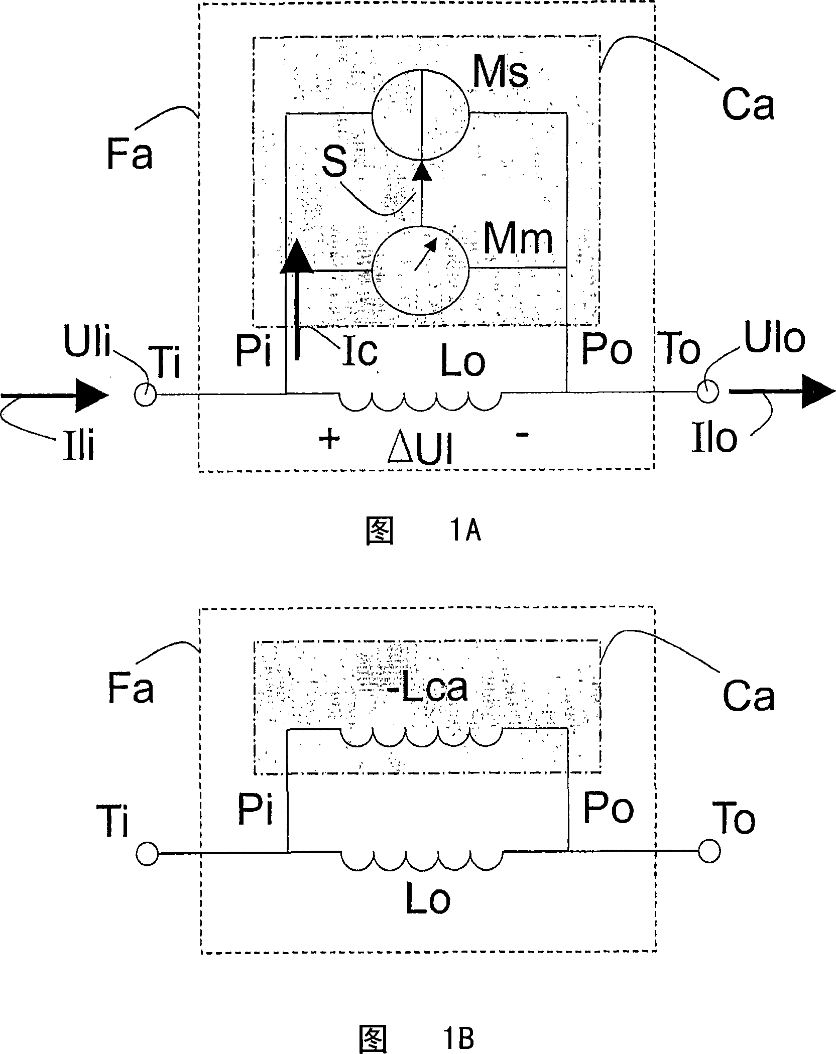
[0030] Fig. 1A shows a schematic circuit diagram of an active EMI filter circuit Fa according to the present invention. The active EMI filter circuit Fa having a filter input terminal Ti and a filter output terminal To further includes a filter inductor Lo and an active circuit Ca. The filter inductor Lo is arranged between the filter input terminal Ti and the filter output terminal To. The active circuit Ca includes a circuit input terminal Pi and a circuit output terminal Po, through which the active circuit is arranged in parallel with the filter inductance Lo, and is also ...


PUM


Abstract

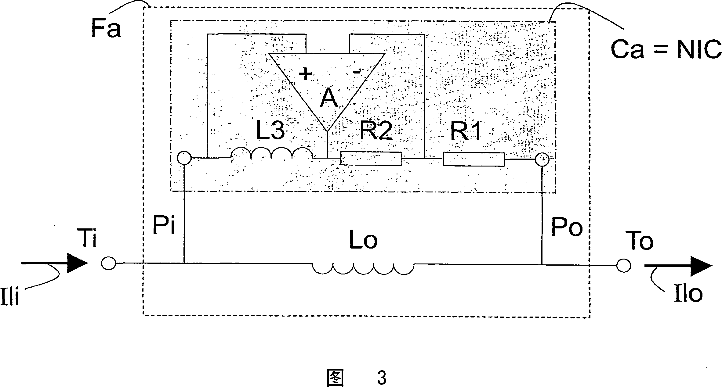
The invention relates to an Electromagnetic Interference (EMI) filter circuit (Fa) for suppressing a Line Conducted Interference (LCI) signal. The EMI filter circuit (Fa) comprises a filter inductance (Lo) to carry a supply current (Isup) between a supply voltage (Vsup) and a load (L). The EMI filter circuit (Fa) further comprises an active circuit (Ca), arranged in parallel with the filter inductance (Lo). The active circuit (Ca) comprises a sensing circuit (Mm) to sense the LCI signal and further comprises a suppressing circuit (Ms) to suppress the LCI signal. In an embodiment of the active EMI filter circuit (Fa), the active circuit (Ca) comprises a negative inductance generating circuit to create a negative inductance value. Selecting the negative inductance generating circuit to create an inductance value (Lca) larger than the inductance value of the filter inductance (Lo) creates a resulting inductance (Lr) which is higher compared to the inductance value of the filter inductance (Lo). In one embodiment, the negative inductance generating circuit comprises a negative impedance converter.

Description

Technical field [0001] The invention relates to an active electromagnetic interference filter for suppressing line-conducted interference signals. [0002] The invention also relates to a common mode suppression filter, and to a power converter including an active electromagnetic interference filter and a device. Background technique [0003] The high-frequency common-mode signal generated by the system affects other electronic devices connected to common coupling points such as mains. Usually can use the filter coil arranged between the system and the mains to obtain the suppression of the high frequency common mode signal. The system, the filter coil and the mains power together form a closed loop. In the simplified equivalent RF diagram of this loop, the common-mode mains impedance is used to represent the mains. The common mode electrical impedance is connected between the reference potential (usually ground) and a terminal of the filter coil. The other terminal of the filter...

Claims


Application Information

Patent Timeline
Patent Type & Authority Applications(China)
IPC IPC(8): H03H1/00H03H11/10
CPCH03H1/0007H03H7/427H03H11/42H03H11/10
Inventor B·特拉A·J·范达尔夫森
Owner KONINK PHILIPS ELECTRONICS NV
Learn More