Double pendulum milling head of AC permanent magnetic synchronization external-rotor-type force moment motor drive

An external rotor motor, permanent magnet synchronous technology, applied in the direction of magnetic circuit rotating parts, drive devices, electric components, etc., can solve the problems of large torque motor, complex braking mechanism, small output torque, etc., and achieve clamping action area. Large, improve the braking effect, the effect of large braking force

Active Publication Date: 2007-08-08
KEDE NUMERICAL CONTROL CO LTD
View PDF0 Cites 41 Cited by
  • Summary
  • Abstract
  • Description
  • Claims
  • Application Information

AI Technical Summary

Problems solved by technology

The present invention also solves the problems of small output torque, complicated braking mechanism, poor braking effect and large volume of the torque motor existing in the prior art of inner rotor torque motor driving the double pendulum milling head

Method used


Image

  • Double pendulum milling head of AC permanent magnetic synchronization external-rotor-type force moment motor drive
  • Double pendulum milling head of AC permanent magnetic synchronization external-rotor-type force moment motor drive
  • Double pendulum milling head of AC permanent magnetic synchronization external-rotor-type force moment motor drive

Examples


Embodiment Construction

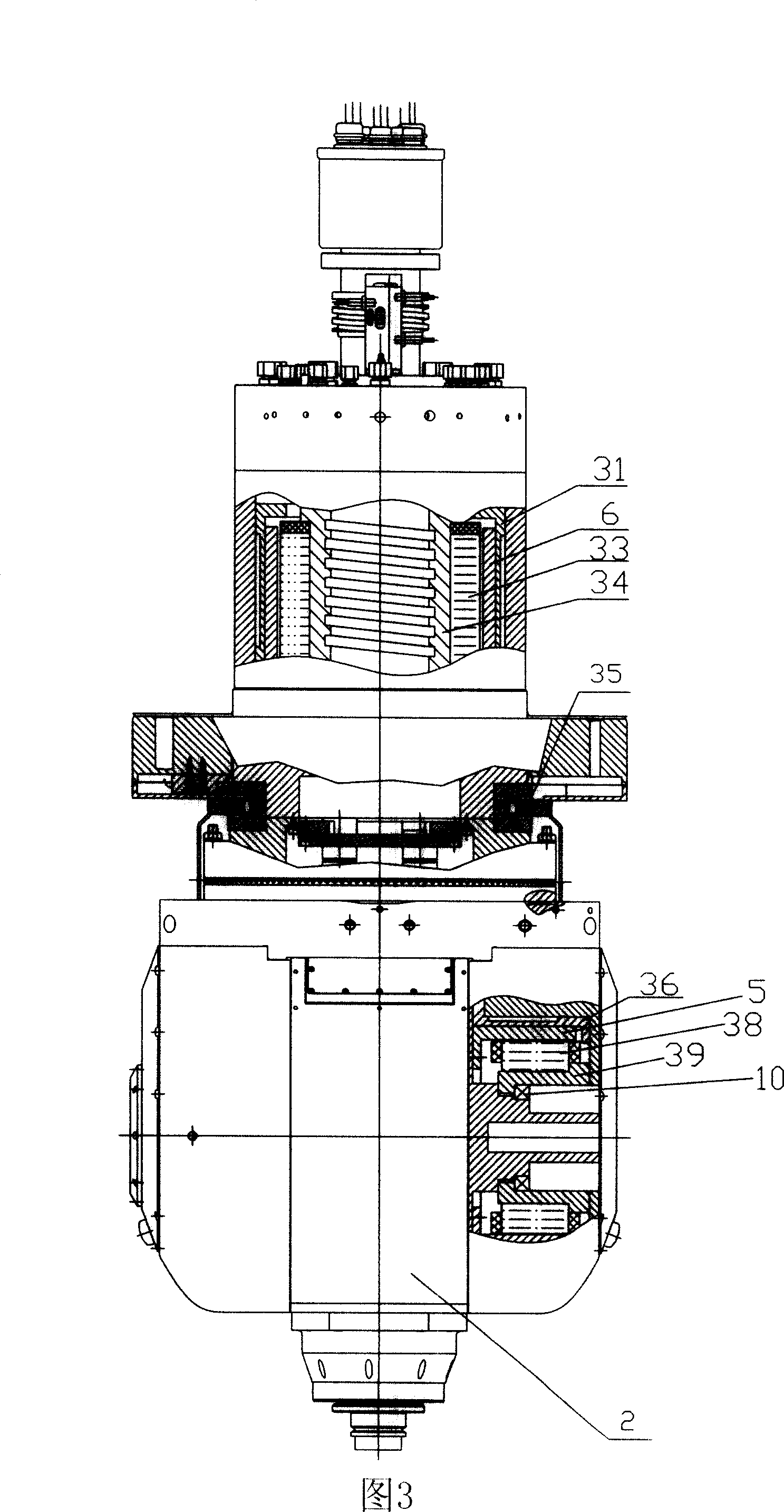
[0028] In order to illustrate the double pendulum milling head of the present invention, a single-axis turntable driven by an AC permanent magnet synchronous outer rotor torque motor is illustrated with reference to FIG. The description of the motor structure is helpful for understanding the driving structure of the double pendulum milling head of the present invention. As shown in Figure 16, the rotor 5' of the motor is directly connected to the turntable table 2', and usually the table 2' is fixed to the end of the rotor 5' by bolts. Simultaneously, the stator 6' positioned at the inner ring of the rotor 5' is connected with the fixed casing 9' of the turntable by bolts. The rotation angle of the turntable is 360°×n (n represents the number of revolutions).

[0029] Permanent magnets are arranged on the inner wall of the rotor 5', and a braking mechanism 4' is arranged outside the rotor. In addition, in order to effectively cool the stator coil windings of the heat source ...


PUM


Abstract

The double pendulum milling head driven by the AC permanent syntactic rotor torque motor having a cross hollow shaft, whose both ends fixed on the rotor of the horizontal torque motor at both ends of the A shaft. Acting as an integral, they are fixed on the rotor of the vertical torque motor of C shaft. In this way, vertical motor driving the milling head to rotate around C shaft, and A shaft horizontal motor driving the pendulum of milling head around A shaft. It complete the complex machining of the working piece through compound motion in two directions matching the high speed revolution of the shaft itself. It is compact in structure, simple of drive, good in rigidity, smaller in mechanical components quantity, higher reaction sensitivity, free from wear and reverse gap, being able to machining for a five-face body with high precision.

Description

technical field [0001] The present invention relates to a milling head that swings in two directions, more specifically, it relates to a built-in torque motor instead of a complex mechanical structure to realize double-swing milling heads moving in two directions so as to realize complex side surface processing of workpieces combined institutions. Background technique [0002] As shown in Figure 1, the traditional mechanical transmission scheme of the double pendulum milling head, the power source realizes the driving of the milling head through the transmission mechanism. Among them, the power source adopts servo motor (servo hydraulic motor), and regards it as an independent unit. The intermediate transmission link adopts gear transmission, rack and pinion transmission or worm gear transmission. Although in this traditional solution, there are fewer electrical connections and the cost of the entire product is lower, the problem is that the machining accuracy of the gear,...

Claims


Application Information

Patent Timeline
Patent Type & Authority Applications(China)
IPC IPC(8): B23Q1/25B23Q5/20B23Q5/10H02K1/20H02K1/27H02K7/10
Inventor 于德海张文峰郑君民鲍文禄蔡春刚王庆鹏李文庆陈伟华游华云徐道明
Owner KEDE NUMERICAL CONTROL CO LTD
Why Eureka
Try Eureka