

Method for preventing end-face spray quenching cracking of quenching piece by changing spray angle
A spray angle, quenching and cracking technology, applied in the direction of quenching agent, quenching device, furnace type, etc., can solve the problems of easy peeling, limited use, inability to use large-sized quenched parts, etc., to achieve simple implementation, slow cooling strength, The effect of increasing infiltration time and area
- Summary
- Abstract
- Description
- Claims
- Application Information
AI Technical Summary
Problems solved by technology
Method used
Image

Examples
Embodiment 1
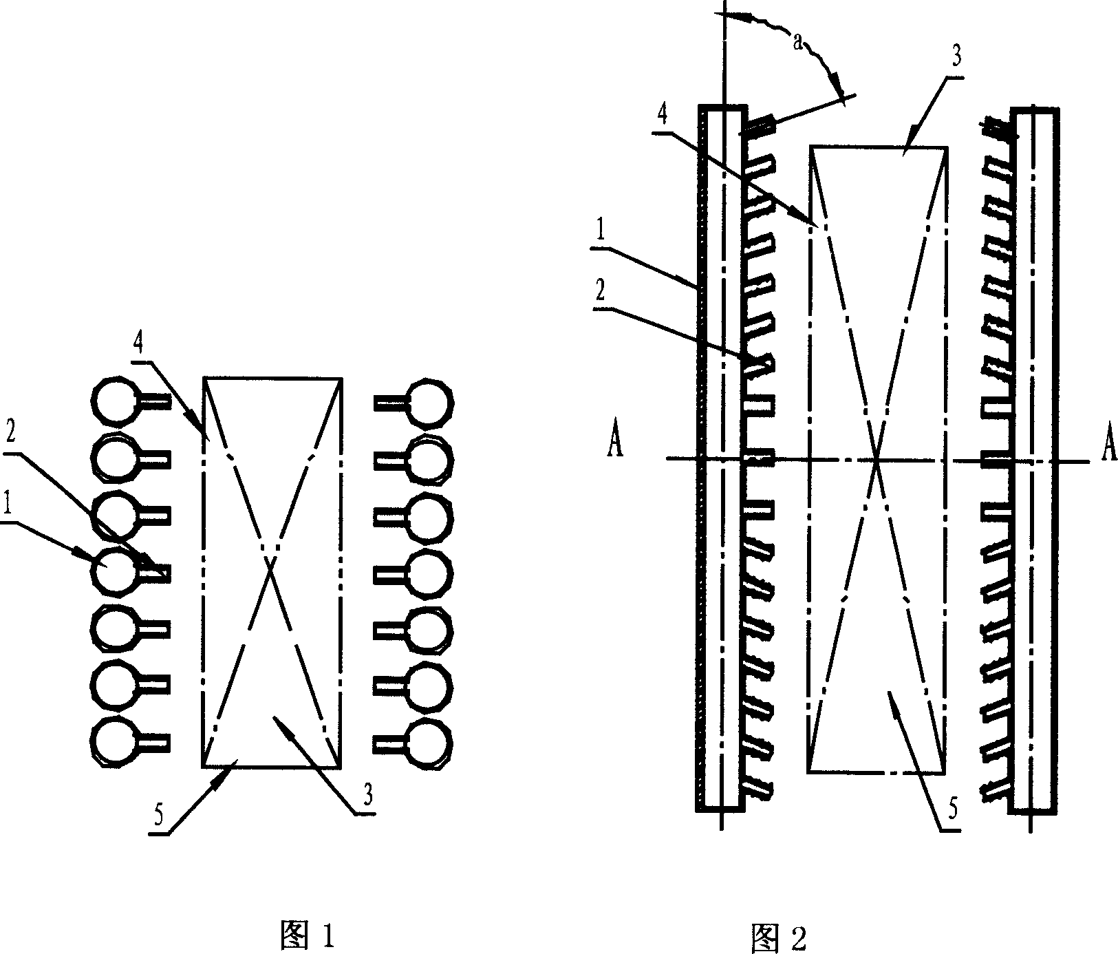
[0016] There is an alloy steel forging, size: length 6000mm×width 1500mm×thickness 500mm, after forging, cut the end face of width 1500mm×thickness 500mm with electric saw, then heat to austenitizing temperature, put the forging on a quenching workbench spray quenching treatment. The quenching medium used is water. The structure of the equipment is to set densely arranged water pipes 1 on both sides of the quenching area, and to install nozzles 2 in the direction where the water pipes 1 face the quenching area. The quenching parts are placed between the densely arranged water pipes 1 on both sides. (Right) The side 4 is parallel to the water pipe 1, the end surface 3 of the quenching part is perpendicular to the water pipe 1, the direction of the nozzle 2 is at an angle a to the water pipe 1, a is between greater than 0° and less than 90°, and the nozzle 2 sprays out The medium and the end face 3 of the quenched part form an angle of 90°-a. The specific working process is: t...
Embodiment 2
[0018] Shafts made of carbon steel, size: Φ500mm×6000mm, after being heated to the austenitizing temperature, hang the shaft horizontally in the quenching area of the quenching equipment, and the quenching process is a combination of spraying, immersion and air cooling Quenching, the quenching medium is a water-soluble quenching medium. The structure of the liquid spray quenching equipment is as follows: densely arranged water pipes 1 and nozzles 2 at an angle a to the water pipes 1 are arranged on both sides of the quenching area in the length direction, and a is between greater than 0° and less than 90°. The specific working process is: the quenching medium flows through the water pipe 1 and is sprayed from the nozzle 2 at an angle a to the water pipe 1 to the left (right) side 4 of the quenching piece and the upper (lower) side 5 of the quenching piece, and the nozzle 2 is sprayed The quenching medium and the end face 3 of the quenching piece are at an angle of 90°-a. As ...
Embodiment 3
[0020] The quenching object is an alloy steel forging, size: length 5000mm×width 2000mm×thickness 300mm, after forging, cut the two end faces of width 2000mm×thickness 300mm with an electric saw, then heat to the austenitizing temperature, hang the forging on the quenching In the quenching area of the equipment, the quenching process is a combination of liquid spray and air cooling, and the quenching medium is water. The water pipe 1 and the nozzle 2 at an angle a to the water pipe are arranged at the corresponding positions of the left (right) side 4 of the quenching piece and the upper (lower) side 5 of the quenching piece, and a is between greater than 0° and less than 90°. The specific working process is: the quenching medium flows through the water pipe 1 and is sprayed from the nozzle 2 at an angle a to the water pipe 1 to the left (right) side 4 of the quenching piece and the upper (lower) side 5 of the quenching piece, and the nozzle 2 is sprayed The quenching medium...
PUM
 Abstract
Description
Claims
Application Information