

Scroll type fluid machine
A fluid machinery and scroll technology, applied in the direction of rotary piston machinery, mechanical equipment, rotary piston pumps, etc., can solve the problems of insufficient cooling and complicated cooling structure, so as to ensure strength and improve heat resistance , the effect of preventing deterioration
Inactive Publication Date: 2007-08-08
HITACHI LTD
View PDF1 Cites 17 Cited by
- Summary
- Abstract
- Description
- Claims
- Application Information
AI Technical Summary
Problems solved by technology
However, at this time, since mechanisms such as the outer diameter of each volute and the auxiliary crank are separated from the drive shaft, sufficient cooling cannot be achieved.
Therefore, in the prior art of Patent Document 2, in addition to allowing the refrigerant to flow through the drive shaft, a cooling fan for cooling the inside of the housing is required, which complicates the entire cooling structure.
Method used
View moreImage
Smart ImageViewing Examples

Examples
Embodiment Construction
[0046] Hereinafter, a scroll type air compressor as an embodiment of the present invention will be described in detail with reference to the drawings, taking a scroll type air compressor as an example.
Login to View More PUM
 Abstract
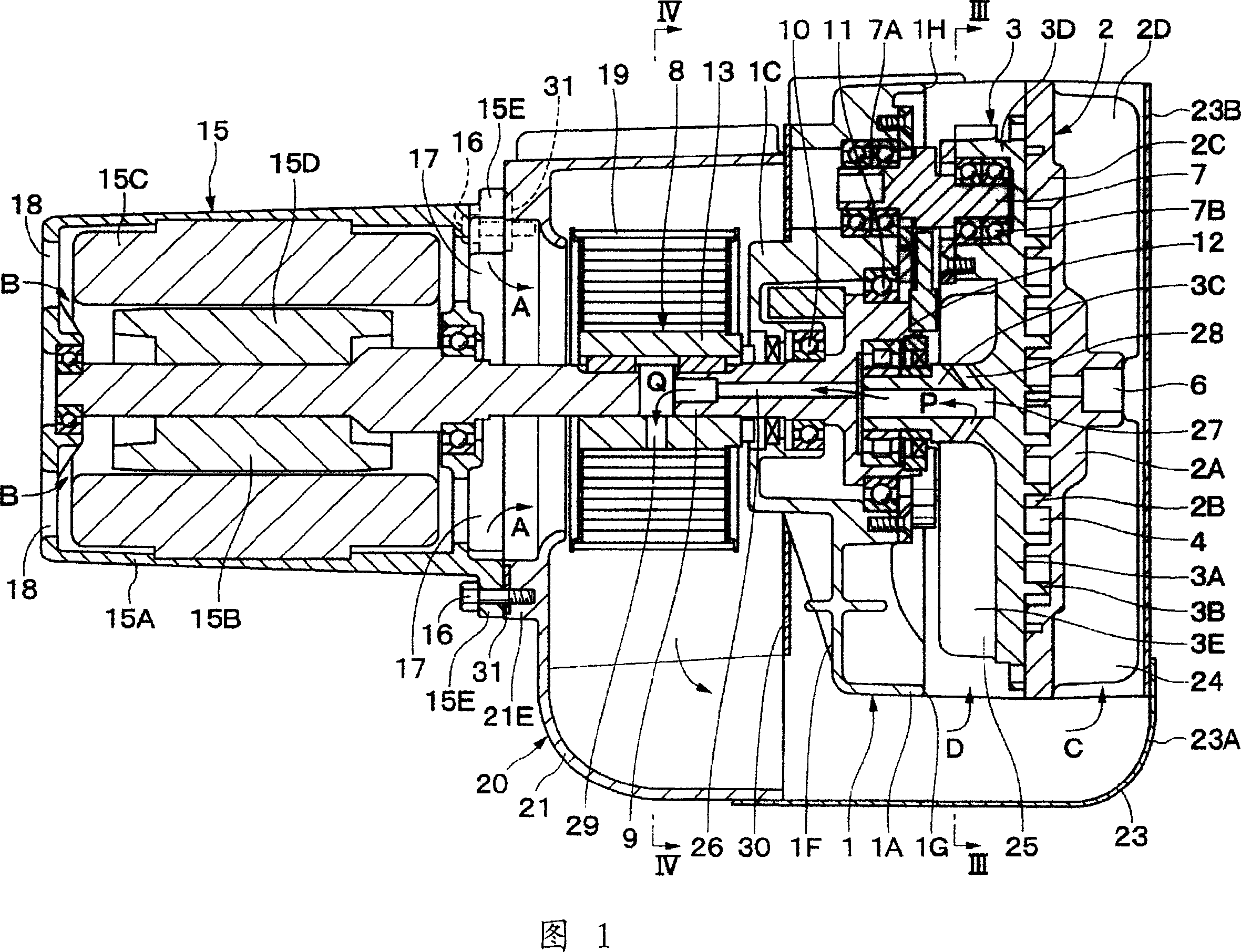
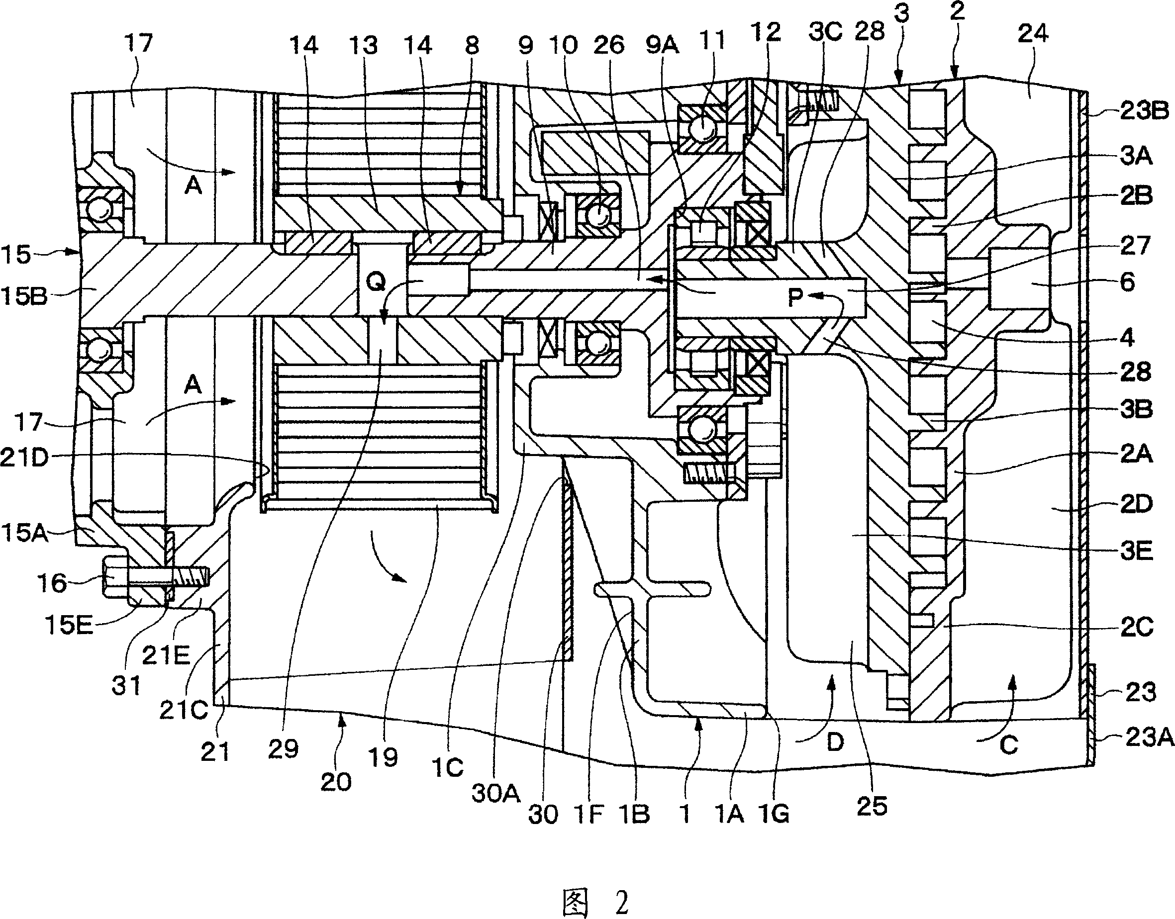
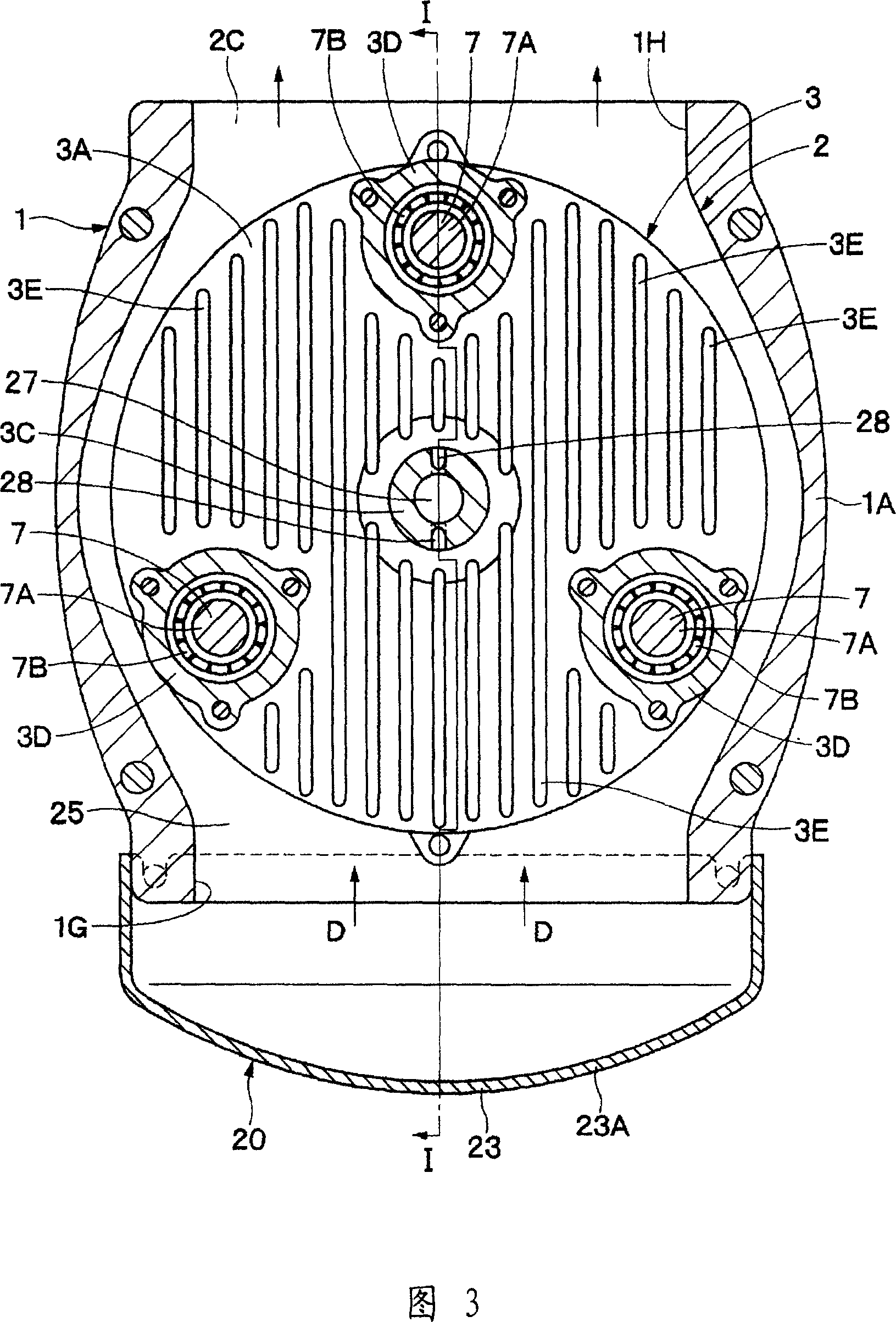
Coolling a main bearing from an inner peripheral side with the usage of cooling air flowing in a casing, and enhance heat resistance by providing a cooling air passage in a driving shaft. The driving shaft 8 rotated and driven by a motor 15 is connected to a connection part 3C of a rotating scroll 3, and the driving shaft 8 is constituted by a main shaft part 9 and a joint part 13. A cooling air passage 26 is provided in the main shaft part 9, and an auxiliary cooling air passage 27 and an inlet side opening 28 are provided in the connection part 3C. An outlet side opening 29 is provided in the joint part 13. When a cooling fan 19 is operated, the cooling air to arrows A, B, C and D directions is generated, and a fixing scroll 2, the rotating scroll 3, and an auxiliary crank 7 are cooled. At that time, a part of the cooling air is made to flow into the cooling air passages 26 and 27 as shown in arrows P and Q, thereby effectively cooling the main bearings 10 and 11 and a rotating bearing 12.
Description
technical field [0001] The present invention relates to a scroll type fluid machine suitable for use as a compressor for air, refrigerant, etc., or a vacuum pump, for example. Background technique [0002] In general, a scroll fluid machine is used as, for example, an air compressor (refer to Patent Document 1). [0003] [Patent Document 1] (Japanese) Unexamined Patent Publication No. 2005-139976 [0004] In this conventional scroll air compressor, a fixed scroll provided on a casing faces a revolving scroll rotatably arranged in the casing. The fixed volute and the revolving volute are respectively provided with scroll-shaped overlapping parts on the surface of the disc-shaped mirror plate, and are divided into a plurality of compression chambers between the overlapping parts of the respective volutes. In addition, a connecting portion connected to the driving side is protrudingly provided on the back surface of the mirror plate of the revolving scroll. [0005] In addi...
Claims
Login to View More Application Information
Patent Timeline
 IPC IPC(8): F04C18/02F04C25/02F04C29/04
CPCF04C18/0215F04C29/0021F04C29/045F04C2210/22F04C2210/26F04C2240/40Y10S415/00Y10S417/00
Inventor信田治彦坂本晋三桥博三原宏之
OwnerHITACHI LTD