Method for on-line measuring refractive index of blooming

A technology of optical film thickness and refractive index, which is used in measurement devices, optical devices, phase influence characteristic measurement, etc. Guarantee, etc.

Active Publication Date: 2007-08-15
HENAN COSTAR GRP CO LTD +1
View PDF0 Cites 7 Cited by
  • Summary
  • Abstract
  • Description
  • Claims
  • Application Information

AI Technical Summary

Problems solved by technology

Therefore, using the peak value of the voltage signal as the voltage value of the evaporation stop point to control the coating thickness is difficult to ensure the accuracy of the evaporation stop point, resulting in low precision of the coating film thickness and poor quality of the

Method used


Image

  • Method for on-line measuring refractive index of blooming
  • Method for on-line measuring refractive index of blooming

Examples


Embodiment Construction

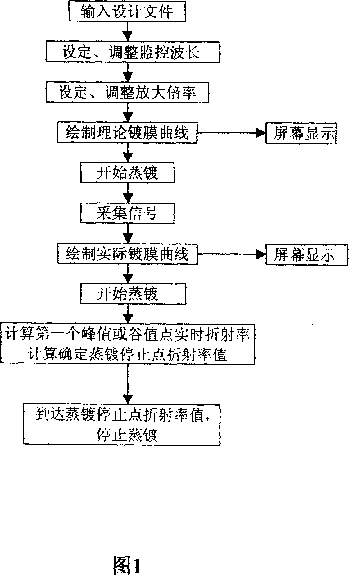
[0020] The method of the present invention is further described in conjunction with Fig. 1:

[0021] (1) According to the TFCalc and Essential Macleod software program, input the design file into the computer. The process design file includes the experimental parameters of the monitoring optical signal wavelength, the refractive index of the film layer, and the absorption rate; the designed film thickness, predetermined packing density, evaporation Theoretical parameters of plating rate, scheduled film forming time, monitoring optical signal wavelength, refractive index of evaporation substrate, vacuum refractive index, and atmospheric refractive index; real-time refractive index (refractive index under current film thickness = initial refractive index × current signal voltage value÷initial signal voltage value), real-time reflectivity (reflectivity under current film thickness=initial reflectivity×current signal voltage value÷initial signal voltage value), film thickness-time ...


PUM


Abstract

This invention relates to one optical film thickness online measurement reflection method, which uses computer for online test on film layer real time reflection rate test and uses real time reflection rate value to correct the monitor voltage signal theory change curve; when the coating film curve processed peak value point and trough point to compute real time reflection rate to stop to correct stop point voltage value and theory curve to display the reflection rate onto screen.

Description

technical field [0001] The invention belongs to the technical field of optical coating monitoring, in particular to a method for online measurement of refractive index of optical film thickness. Background technique [0002] At present, in optical coating, an optical monitoring system is generally used to monitor and control the coating film thickness, that is, the light beam emitted by the light source system is modulated, collimated, and split, and then projected onto the comparison sheet, and then the film thickness optical signal reflected by the comparison sheet Projected on the photoreceptor, after photoelectric conversion, a voltage signal with film thickness information is obtained. When monitoring, the voltage signal instrument is manually observed. When the voltage gauge needle swings to a certain extreme value, it is considered that the film thickness requirement has been met and the evaporation is stopped. However, due to the influence of various random factors ...

Claims


Application Information

Patent Timeline
IPC IPC(8): G01B11/06G01N21/41
Inventor 赵升林孙龙菊池和夫
Owner HENAN COSTAR GRP CO LTD
Why Eureka
Try Eureka