

Sealed liquid lubricator
A liquid sealing and lubricating device technology, applied in transportation and packaging, tracked vehicles, motor vehicles, etc., can solve problems such as increased driving resistance, insufficient strength of thrust washers, and reduced service life
- Summary
- Abstract
- Description
- Claims
- Application Information
AI Technical Summary
Problems solved by technology
Method used
Image

Examples
Embodiment 1
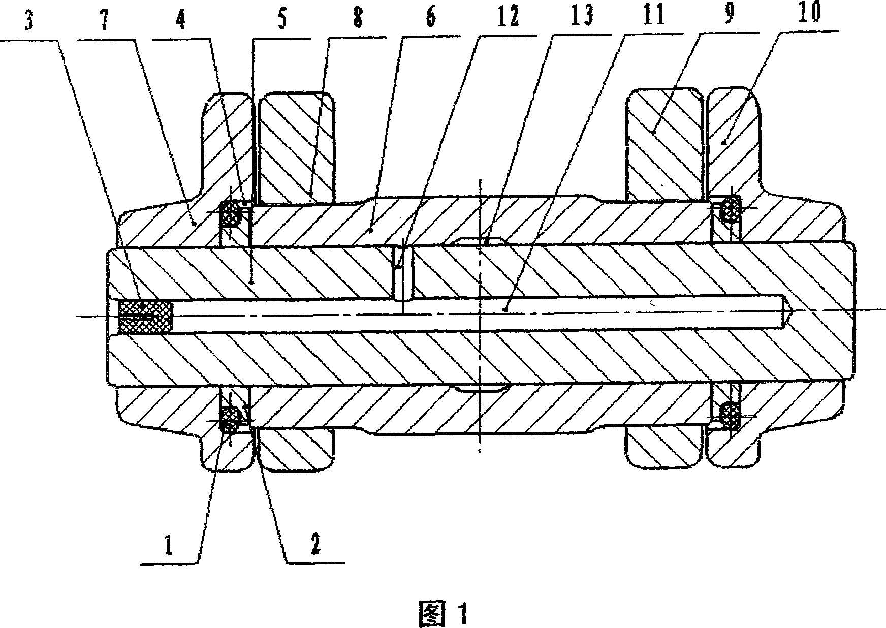
[0070] With reference to accompanying drawing 1, sealed lubricating track of the present invention is made up of elastic rubber ring 1, metal ring 2 and cone blind hole rubber plug 3. It involves chain link counterbore 4, pin shaft 5, pin sleeve 6, chain links 7, 8, 9, 10, center oil hole 11, through hole 12, oil storage chamber 13.
[0071] Manually fit the elastic rubber ring 1 on the outer surface of the metal ring 2, and press them into the counterbore 4 of the chain link together. At this time, there is a certain amount of interference fit between the outer surface of the rubber ring and the inner surface of the counterbore of the chain links 7 and 10, and the metal ring is suspended in the center of the counterbore. Accompanying drawing 4 is assembled with pin sleeve 6, and makes the left and right sleeve ends connect chain link split surface in one plane (last assembling shaft end connects chain link 18). Then the chain links 7, 10 and the chain links 8, 9 equipped wit...
Embodiment 2
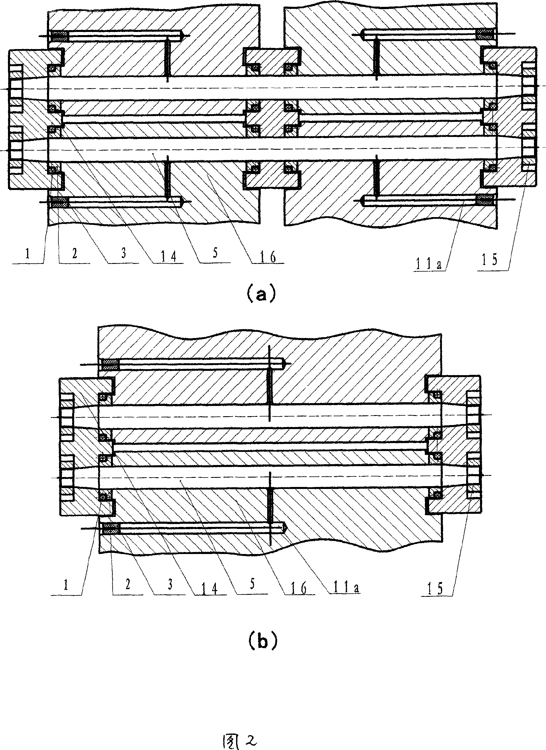
[0076] Accompanying drawing 2 is double-pin shaft pinless center oil hole sealed lubricating track, which is another type of sealed lubricating track according to the present invention. It consists of an elastic rubber ring 1, a metal ring 2, and a cone blind hole rubber plug 3. Relate to double taper hole connecting plate 14, track pin shaft 5, track shoe 16, anti-loosening fastening nut 15, oil hole 11a (in track shoe).
[0077] The track shoe 16 is a single piece, and there are two pin holes in each track shoe 16. It should be pointed out that: when the two pin holes are processed, there should be multiple oil storage chambers on the middle surface, (omitted in the drawings) to Good for oil storage. This kind crawler track divides two kinds of assembling modes, as accompanying drawing 2 (a), 2 (b), be to be connected by double taper hole coupling plate 14 between the plate and the plate. Double taper hole connecting plate 14 is equivalent to driven gear, and driving gear ...
Embodiment 3
[0080] Accompanying drawing 5 is double-sealed roller type lubricating track, adopts pin shaft without center oil hole, the mode that oil storage chamber is in the roller, is another type of sealed lubricating track of the present invention. It consists of elastic rubber rings 1, 1a, metal rings 2, 2a, and cone blind hole rubber plug 3. Involving roller 20, needle roller bearing 33, pin shaft 5, pin sleeve 6, oil storage cavity 26,35, through hole 34, chain link counterbore 4, inner chain link 8, outer chain link 7.
[0081] In conjunction with embodiment, the description is as follows with reference to accompanying drawing 5: this kind of double sealing device, one is installed in the inside, and one is installed in the outside, namely the double sealing that is made up of two single sealing devices of the same effect. It is equivalent to adding a roller on the outer surface of the pin sleeve 6 in the accompanying drawing 1. The difference is that the load-bearing wheel of th...
PUM
 Abstract
Description
Claims
Application Information