Water delivery tank and its welding method

A welding method and water tank technology, which are applied in solar thermal power generation, heating devices, solar thermal devices, etc., can solve the problems of leakage at the weld, limited heat exchange area, low heat exchange efficiency, etc., and can eliminate the leakage at the weld. Hidden danger, high welding reliability, and the effect of eliminating gaps

Inactive Publication Date: 2007-08-22
CONSOL CHANGZHOU ENERGY
View PDF0 Cites 1 Cited by
  • Summary
  • Abstract
  • Description
  • Claims
  • Application Information

AI Technical Summary

Problems solved by technology

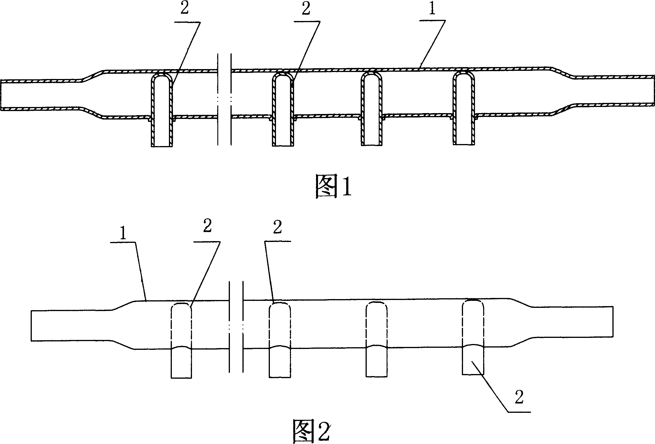
[0002] Only one end of the bushing of the water channel of the original solar collector is inserted into the main pipe, and the bushing does not pass through the main pipe, so the heat transfer area is limited and the heat transfer efficiency is low; moreover, the bushing is subject to pressure during assembly The force is prone to tilt, and it cannot be guaranteed to be perpendicular to the water main pipe, as shown in Figure 1 and 2, which brings inconvenience to the installation of the whole machine
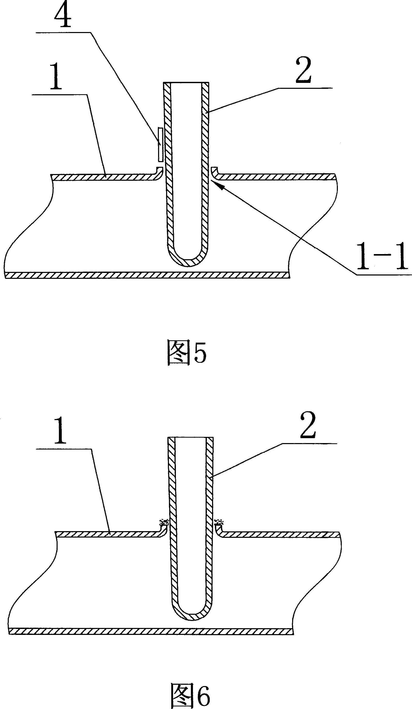
[0003] As shown in Figures 5 and 6, the traditional method of welding the water channel is to insert the top of the sleeve into the through hole of the water main pipe and place it in the water main pipe so that the tail end of the sleeve is exposed outside the through hole. Manual welding with welding rods. Weld firmly the joint between the sleeve and the flange on the water main pipe. The welding place is formed by melting and accumulating copper welding rods at high temperature. Due to local heating, the welding rods cannot flow well after melting and spread to the welded joints. Around the seam and in the depth, it can only accumulate at the seam mouth, resulting in the incomplete fusion of the electrode and the base metal, which will have a negative impact on the quality of the weld
The welding reliability of this welding method is not high, there is a hidden danger of leakage at the weld seam, and the operation is inconvenient

Method used


Image

  • Water delivery tank and its welding method
  • Water delivery tank and its welding method
  • Water delivery tank and its welding method

Examples


Embodiment Construction

[0017] The present invention is described in further detail below in conjunction with the embodiment that accompanying drawing provides.

[0018] As shown in Figures 1 and 2, in the original flume, only one end of the sleeve 2 is inserted into the water main 1, and the sleeve 2 does not pass through the water main 1.

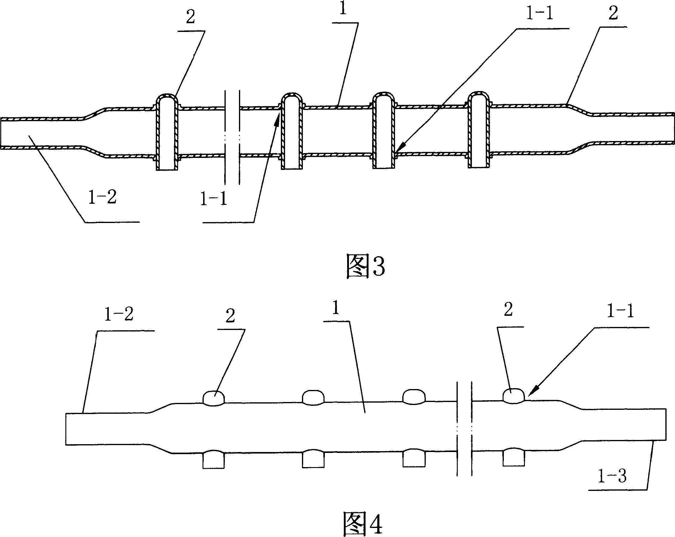
[0019] As shown in Figures 3 and 4, the water running trough of the present invention includes a water running main pipe 1 and a casing 2. The water running main pipe 1 has several transverse through holes 1-1, and the through holes 1-1 are fixedly equipped with a sleeve pipe 2. , both ends of the casing 2 are exposed outside the water main pipe 1 .

[0020] As shown in Figures 3 and 4, the two ends of the water main pipe 1 respectively have a water inlet pipe section 1-2 and a water outlet pipe section 1-3 whose outer diameter is smaller than the outer diameter of the pipe section in the middle of the water main pipe 1.

[0021] As shown in Figures 5 and 6, it...


PUM


Abstract

The invention discloses a water channel used for the solar energy collector and the sealing method. The water channel includes the main water pipe and bushing. The main pipe has many cross through holes which is fixed with the bushings. The two ends of the bushing are all out of the main water pipe. The method is: the bushing is inserted into the cross through hole and the two ends are all out of the hole, then are the below processes: the brazing silk ring is set in the joint between the main water pipe and the bushing which is sealed by the high frequency soldering machine, then the main water pipe and the bushing are all be turned over to make the other sealing joint up which is set on the brazing silk ring. The invention has the big heat exchanging area and high reliability, so the joint can not leak.

Description

technical field [0001] The invention relates to a water running trough used for a solar heat collector and a welding method thereof. Background technique [0002] Only one end of the bushing of the water channel of the original solar collector is inserted into the main pipe, and the bushing does not pass through the main pipe, so the heat transfer area is limited and the heat transfer efficiency is low; moreover, the bushing is subject to pressure during assembly The power is prone to inclination, and it cannot be guaranteed to be perpendicular to the water main pipe, as shown in Figures 1 and 2, which brings inconvenience to the installation of the complete machine. [0003] As shown in Figures 5 and 6, the traditional method of welding the water channel is to insert the top of the sleeve into the through hole of the water main pipe and place it in the water main pipe so that the tail end of the sleeve is exposed outside the through hole. Manual welding with welding rods. ...

Claims


Application Information

Patent Timeline
Patent Type & Authority Applications(China)
IPC IPC(8): F24J2/46
CPCY02E10/40
Inventor 吴克明
Owner CONSOL CHANGZHOU ENERGY
Why Eureka
Try Eureka