Sandwich transducer type longitudinal and bending linear ultrasound motor with frequency-modulating variable-amplitude rod

A linear ultrasonic motor, horn technology, applied in piezoelectric effect/electrostrictive or magnetostrictive motors, generators/motors, electrical components, etc., can solve the problem of inability to form product serialization, low motor efficiency, problems such as high noise, to achieve the effects of low noise, reduced loss, and high efficiency

Inactive Publication Date: 2007-08-22
HARBIN INST OF TECH
View PDF0 Cites 26 Cited by
  • Summary
  • Abstract
  • Description
  • Claims
  • Application Information

AI Technical Summary

Problems solved by technology

[0003] The purpose of the present invention is to provide a sandwich transducer type longitudinal bending linear ultrasonic motor with a frequency modulation horn, which can solve the exis

Method used


Image

  • Sandwich transducer type longitudinal and bending linear ultrasound motor with frequency-modulating variable-amplitude rod
  • Sandwich transducer type longitudinal and bending linear ultrasound motor with frequency-modulating variable-amplitude rod
  • Sandwich transducer type longitudinal and bending linear ultrasound motor with frequency-modulating variable-amplitude rod

Examples


specific Embodiment approach 1

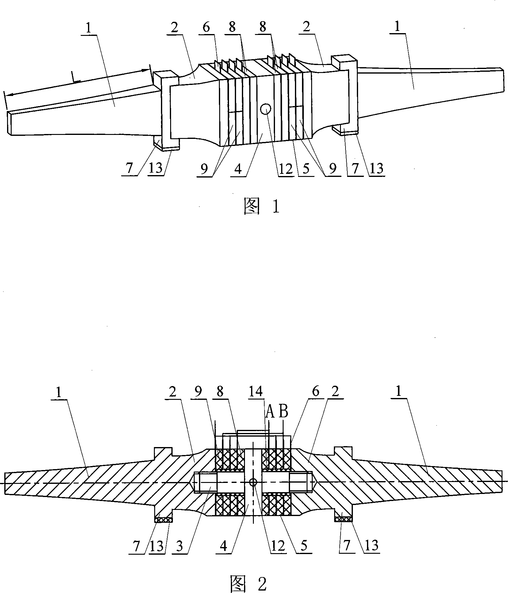
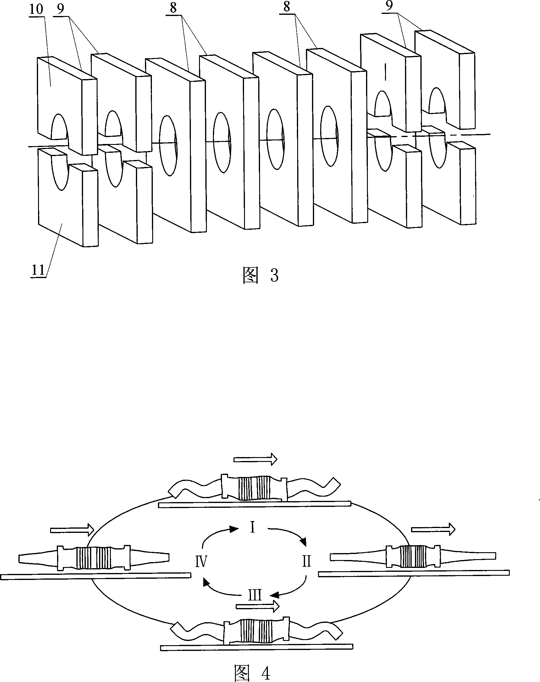
[0006] Specific embodiment 1: This embodiment is described in conjunction with Fig. 1 to Fig. 3. This embodiment is composed of a sandwich transducer and a driving foot 7; , flange 4, piezoelectric ceramic sheet group 5, and thin copper sheet 6; the middle position on the stud 3 is provided with a flange 4, the stud 3 on the left side of the flange 4 and the right side of the flange 4 The studs 3 are equipped with piezoelectric ceramic sheet groups 5 respectively, and thin copper sheets as electrodes are respectively installed between the piezoelectric ceramic sheets of the piezoelectric ceramic sheet group 5 and between the piezoelectric ceramic sheet group 5 and the end cover 2. 6. The piezoelectric ceramic sheet group 5 and the thin copper sheet 6 are fastened together with the large end of the end cover 2 through the stud 3, and the small end of the end cover 2 is affixed to the large end of the FM horn 1 through the driving foot 7 , the driving foot 7 is located at the an...

specific Embodiment approach 2

[0008] Specific Embodiment 2: This embodiment is described with reference to FIG. 1 and FIG. 2 . In this embodiment, a small conical hole 12 is drilled on the front side and the rear side of the flange 4 at the overlapping nodes of the longitudinal bending vibration. As the clamping point of the pre-tightening force mechanism of the linear ultrasonic motor, it is used to apply the pre-tightening force to generate driving friction. Choosing to drill two small conical holes 12 at this position can prevent resonance frequency drift and vibration distortion, and reduce energy loss. Other components and connections are the same as those in the first embodiment.

specific Embodiment approach 3

[0009] Specific embodiment three: This embodiment is described in conjunction with Fig. 1 and Fig. 2. The difference between this embodiment and specific embodiment one is: this embodiment also adds a hard ceramic friction plate 13; the hard ceramic friction plate 13 Bond with the lower end surface of the driving foot 7. Such setting can prevent the driving foot 7 from wearing out and prolong the service life of the driving foot 7 .


PUM


Abstract

A linear ultrasonic motor of sandwich transducer type with FM variable - amplitude rod is prepared as firm-connecting longitudinal-flexural vibration piezoelectric ceramic wafer and thin copper plate with big end of end cover through double-screw bolt and small end of end cover to big end of FM variable - amplitude rod through driving foot, arranging said driving foot and flexural vibration piezoelectric wafer separately at vibration wave loop of flexural vibration for setting polarization directions of flexural and longitudinal vibration piezoelectric ceramic wafer and setting length of variable-amplitude rod to be 1/2 of longitudinal vibration wavelength.

Description

technical field [0001] The invention relates to a linear ultrasonic motor and belongs to the technical field of piezoelectric ultrasonic motors. Background technique [0002] Ultrasonic motor is a motor that uses ultrasonic vibration energy and generates driving force through friction. It has the advantages of low speed and high torque (thrust), no need for a gear change mechanism, no electromagnetic interference, fast response, and self-locking when power is off. It is widely used as a piezoelectric driver. 2001 Japan "Applied Physics" magazine (Jpn.J.Appl.Phys) No. 40 p3773~3776 pages, titled "A High Power Ultrasonic Motor Using a Longitudinal and Bending Hybrid Bolt-Clamped Langevin Type Transducer" (a kind of bolt-clamped Langevin Type Transducer) A high-power ultrasonic motor with a sandwich-type longitudinal-bending composite transducer fastened) proposed a linear ultrasonic motor. Since the two sets of bending vibration ceramic plates are located at the two antinodes...

Claims


Application Information

Patent Timeline
IPC IPC(8): H02N2/02H02N2/04
Inventor 陈维山石胜君刘军考谢涛
Owner HARBIN INST OF TECH
Why Eureka
Try Eureka