Resin layer surface micro structure mould-band rolling wheel shaping method and optical film

A molding method and resin layer technology, applied in optics, optical components, nonlinear optics, etc., can solve the problems of optical film microstructure defects, greatly increased manufacturing costs, unusable rollers, etc., to improve product quality and production efficiency. , to ensure the integrity and precise effect of the finished product

Inactive Publication Date: 2007-08-29
APTICON
View PDF3 Cites 31 Cited by
  • Summary
  • Abstract
  • Description
  • Claims
  • Application Information

AI Technical Summary

Problems solved by technology

However, when the roll forming method is used to manufacture these optical films, the partially cured UV glue is easy to adhere to the peaks and grooves of the metal roller with high surface energy or low contact angle (contact angle), making it subsequent in continuous During embossing, it is easy to produce microstructural defects on the optical film, or cause the roller to be unusable, which limits its application range, and the roller is expensive and needs to be replaced every now and then, which greatly increases the manufacturing cost and shows its shortcomings

Method used


Image

  • Resin layer surface micro structure mould-band rolling wheel shaping method and optical film
  • Resin layer surface micro structure mould-band rolling wheel shaping method and optical film
  • Resin layer surface micro structure mould-band rolling wheel shaping method and optical film

Examples


Embodiment 1

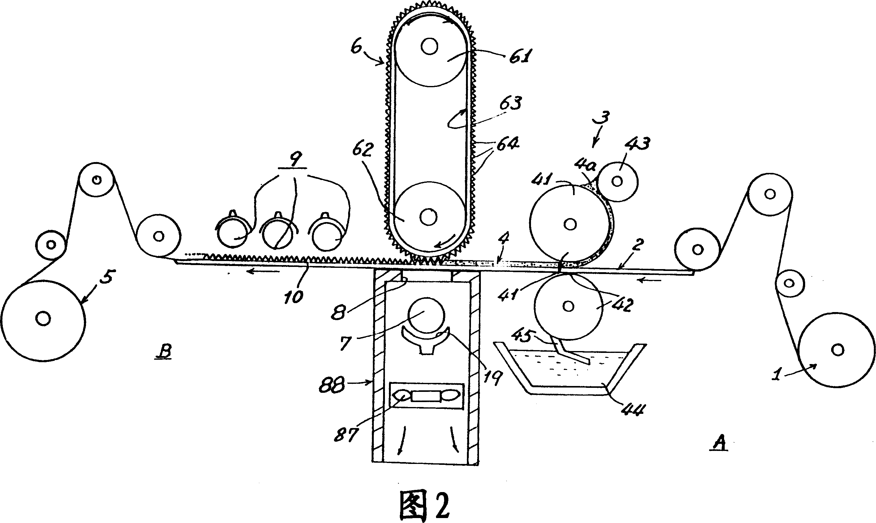
[0050] FIG. 2 shows the first embodiment of the present invention related to a method for forming the surface microstructure of a photosensitive resin layer (such as a UV adhesive layer). The molding method is to make a plastic substrate 2 feed through a gluing feed roller group 3 from its substrate roll 1 (i.e., the A end of FIG. 2 ), and make a gluing wheel of the gluing roller group 3 41 Coating a photosensitive resin layer (such as a UV adhesive layer) 4 on at least one side of the plastic substrate 2, and embossing it on the resin layer 4 through a forming mold belt roller set 6 The required microstructure (including prism array, etc.). Wherein said molding die belt roller set is composed of an upper roller 61 and a lower roller 62 arranged in parallel, wherein the upper roller 61 is a driving roller, and the lower roller 62 is a passive roller. In addition, a forming mold belt 63 (which can be a continuous endless belt (endless)) is wound around the upper and lower roll...

Embodiment 2

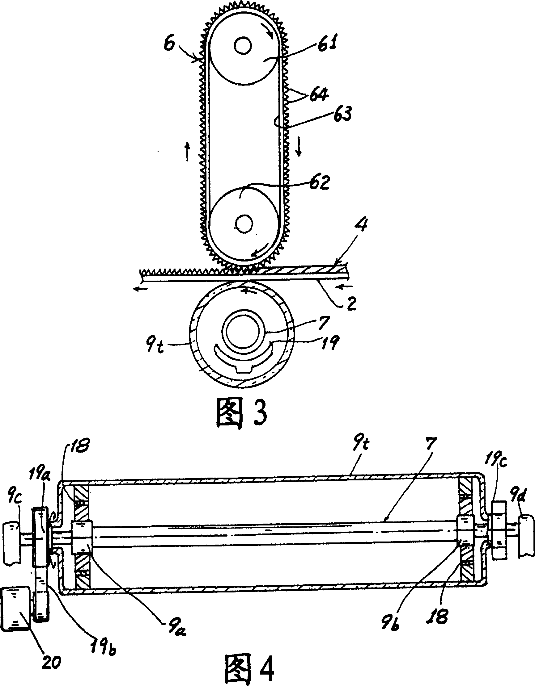
[0057] As shown in Fig. 3 and Fig. 4, the back pressure element of the forming die belt roller group 6 used in the present invention can be modified from the structure 88 shown in Fig. 2 to a back pressure element 9t that is a hollow cylinder (can be It is selected from transparent materials that can penetrate ultraviolet rays, such as quartz), and its axial direction is parallel to the other side of the forming roller group 6; and the two sides of the surface preliminary curing UV lamp 7 are installed on a pair of fixed lamps Between the seats 9a, 9b, two fixed lamp holders 9a, 9b (as shown in Figure 4) are fixedly mounted on a pair of fixed bases 9c, 9d, and are respectively pivotally connected to the peripheral edges of the two fixed lamp holders 9a, 9b. A pair of bearings 18, a hollow quartz tube 9t is stably fixed on the outer edges of the two bearings 18, and a driving end 19a of the hollow quartz tube 9t is connected to a transmission 19b, and a motor 20 is used to drive...

Embodiment 3

[0060] As shown in Figure 5, another preferred design of the forming mold belt roller set 6 used in the present invention includes: a pair of upper rollers 61a, 61b are linked and driven by a synchronous motor, and the lower roller 62 , A forming mold belt 63 is wound on the upper rollers 61a, 61b and the lower rollers 62. The roller 61a is used to take up the mold belt 63 unwound from the roller 61b. On the mold belt surface of this forming mold belt 63, desired microstructure, ornamental pattern or pattern 64 have been made; A back pressure plate 88 is axially parallel and pivotally mounted on the other side of the described forming roller group 6, and makes The distance between the back pressure plate 88 and the forming roller set 6 can be adjusted to adjust the pressure applied by the forming roller set 6 on the photosensitive resin (such as UV glue) layer 4 of the plastic substrate 2, When the plastic substrate 2 coated with the photosensitive resin layer (such as UV glu...


PUM

PropertyMeasurementUnit
refractive indexaaaaaaaaaa

Abstract

The invention relates to a method to form a Tape-to-Roll(TTR) about the surface micro-structure of optical activity resin layer, the related surface micro-structure is embossed molding by the molding belt with anti-adhesion and low surface energy and optical activity resin(for example: UV adhesive) before the curing, embossed at the same time through an surface initial curing UV lights, the optical activity resin or viscose before entering entirely Curing UV lights curing the surface of optical activity resin, the loss of mobility, in order to avoid forming embossed micro-structure produce stampede or deformation, at last the surface micro-structure of optical activity resin layer of initial curing is completely curing by curing UV lights. The invention also includes optical film which is manufactured according to this method.

Description

technical field [0001] The present invention relates to a mold belt-to-roll forming method of the surface microstructure of a resin layer and an optical film, in particular to a mold belt-to-roll forming method of the surface microstructure of a photosensitive resin layer and an optical film prepared by the method . Background technique [0002] Some liquid crystal displays have used a large amount of brightness enhancement film to increase the light output brightness of the liquid crystal display, and make the light output direction approach to the orthogonal or coaxial direction to the liquid crystal display screen. Brightness enhancement films are generally used, with microstructures on the surface, and the microstructures can include prism arrays. The optical structure of the prism arrays can effectively increase the number of coaxial light rays and reduce the energy of the required light source to produce the desired coaxial brightness. The backlight module in the liqu...

Claims


Application Information

Patent Timeline
Patent Type & Authority Applications(China)
IPC IPC(8): G02B5/04B29D11/00G03F7/00G02F1/1335
Inventor 林清彬
Owner APTICON
Why Eureka
Try Eureka