
Distortion measurement and correction method for CCD shooting system and comprehensive test target

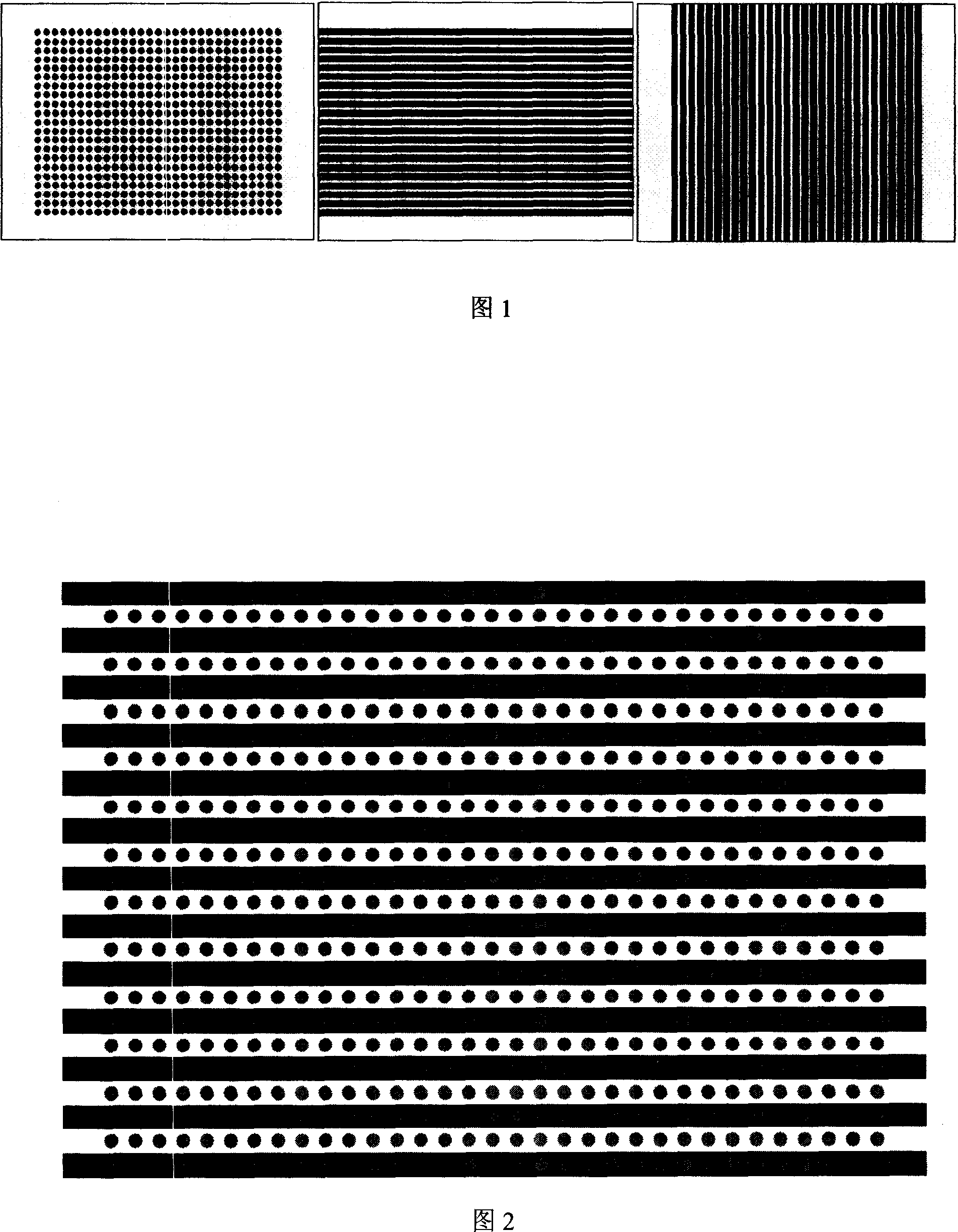
A comprehensive testing, measurement and correction technology, applied in the field of distortion correction, can solve the problems of difficulty in the correspondence between the target sampling point and its image point position, low accuracy of the target sampling point position, etc., and achieve the effect of high-precision testing and calibration.

Inactive Publication Date: 2007-08-29
BEIJING INSTITUTE OF TECHNOLOGYGY
View PDF0 Cites 27 Cited by
  • Summary
  • Abstract
  • Description
  • Claims
  • Application Information

AI Technical Summary

Problems solved by technology

[0006] The purpose of the present invention is to overcome above-mentioned deficiencies in the prior art, propose a kind of distortion measurement correction method based on the CCD camera system of comprehensive test target, solve the position accuracy of target sampling point is not high and target sampling point and its corresponding difficulty of image point position Especially suitable for distortion measurement and correction of large field of view and short focal length CCD camera system

Method used


Image

  • Distortion measurement and correction method for CCD shooting system and comprehensive test target
  • Distortion measurement and correction method for CCD shooting system and comprehensive test target
  • Distortion measurement and correction method for CCD shooting system and comprehensive test target

Examples


Embodiment Construction

[0021] In order to better understand the technical solutions of the present invention, a further detailed description will be given below in conjunction with the accompanying drawings and embodiments.

[0022] Adopt the inventive method, specifically carry out as follows:

[0023] 1. Establish the transformation relationship between the world coordinate system and the camera coordinate system: the world coordinate system (O, x w ,y w ,z w ) first rotates an angle ω around the x-axis, then rotates an angle  around the y-axis, and finally rotates an angle φ around the z-axis to obtain the camera coordinate system (O c , x c ,y c ,z c ), the world coordinate system and Transformation relationship between camera coordinate systems:

[0024] x c y c ...


PUM


Abstract

The integrated testing target is composed of black / white interband and gray object points on the black / white interband. The method includes steps: establishing transformation relations between world coordinate system (CS) and camera CS, between pixel CS and image CS, between camera CS and image CS in sequence; collecting imaging polar coordinates (PC) of distortion image; plotting ideal imaging PC without distortion; determining coincidence relation between coordinate points (CP) of ideal image and CP of distortion image, and building polynomial model; based on polynomial coefficient to measure and correct distortion. The invention considers combined information of point target and row target for the integrated testing target. Using the integrated testing target replaces traditional three discrete target boards so as to solve issues of low position precision of target sample points, and difficult to make corresponding positions between target sampling points and image points.

Description

technical field [0001] The invention relates to a distortion measurement correction method and a comprehensive test target of a CCD camera system, which can be applied to television guidance, aerospace remote sensing, aerial surveying and mapping systems, medical electronic endoscopes, photoelectric guidance and positioning, stereo vision, robot navigation, monitoring and automatic Distortion correction for assembly, robot vision, etc., especially suitable for distortion measurement and correction of CCD camera systems with large field of view and short focal length characteristics. It belongs to the field of optical imaging. Background technique [0002] Due to the small size, simple optical mechanism and large field of view of the CCD camera system and lens with a large field of view and short focal length, the captured image has great distortion, which seriously affects the image quality. [0003] Distortion measurement and correction research of CCD camera system is usu...

Claims


Application Information

Patent Timeline
Patent Type & Authority Applications(China)
IPC IPC(8): H04N17/00G06T7/00
Inventor 周桃庚林家明陈凌峰张旭升何川沙定国
Owner BEIJING INSTITUTE OF TECHNOLOGYGY
Learn More