Centrifugal impeller and pump apparatus

A centrifugal and impeller technology is applied to centrifugal impellers and a pump equipment. The pump equipment field with such centrifugal impellers can solve the problems of reduced impeller performance, longer meridian length, and increased friction loss.

Active Publication Date: 2007-08-29
EBARA CORP
View PDF0 Cites 0 Cited by
  • Summary
  • Abstract
  • Description
  • Claims
  • Application Information

AI Technical Summary

Problems solved by technology

[0004] However, as shown in FIGS. 2A and 2B , if a curve L1 or a straight line L2 is formed at the wheel housing 120, the flow path 140 will not be able to flow if the flow rate of the centrifugal impeller is small and the pump head is high, that is, the specific speed (Ns) is small. The meridional length o

Method used


Image

  • Centrifugal impeller and pump apparatus
  • Centrifugal impeller and pump apparatus
  • Centrifugal impeller and pump apparatus

Examples


Embodiment Construction

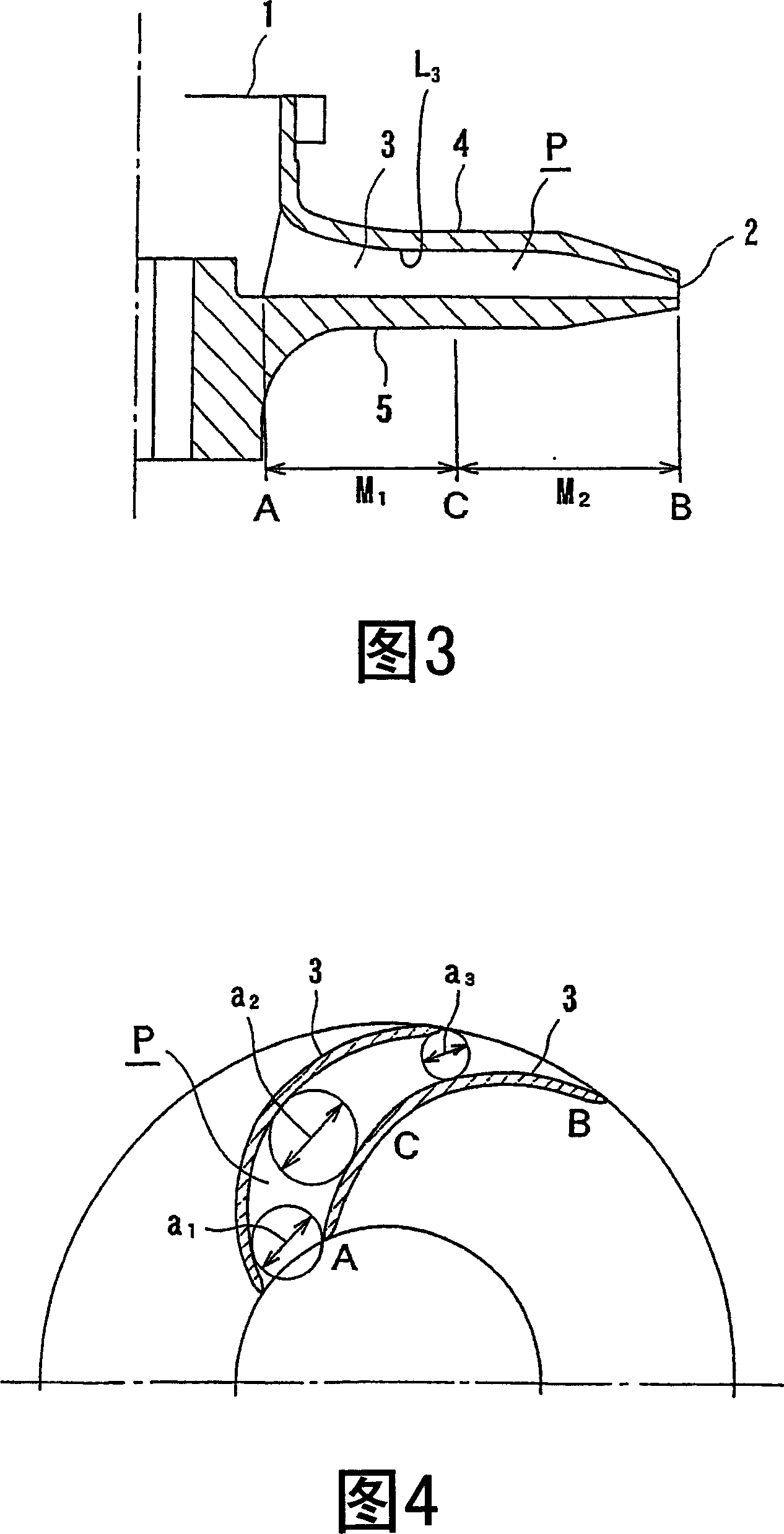
[0026] A centrifugal impeller according to one embodiment of the present invention will be described below with reference to the drawings. Fig. 3 is a meridian section view of the centrifugal impeller according to the first embodiment of the present invention, and Fig. 4 is a section view of the centrifugal impeller shown in Fig. 3 .

[0027] As shown in FIGS. 3 and 4 , the centrifugal impeller includes a plurality of blades 3 (only two adjacent blades 3 are shown in FIG. 4 ), a shroud (tip) 4 , and a hub 5 . The blade 3 is arranged between the wheel cover 4 and the hub 5 along the axial direction of the centrifugal impeller, and is arranged between the impeller inlet 1 on the central side of the centrifugal impeller and the impeller outlet 2 on the circumferential side of the centrifugal impeller. The blades 3 are angularly arranged at equal intervals on the circumferential direction of the centrifugal impeller and extend outward in a spiral manner. A plurality of flow paths...


PUM


Abstract

The centrifugal impeller includes a plurality of blades (3), a plurality of fluid paths (P) for delivering a fluid from an impeller inlet (1) to an impeller outlet (2), and a shroud (4) and a hub (5) for forming the fluid paths (P). Each of the fluid paths (P) is formed between adjacent two of the blades (3). A curved line (L3) of the shroud (4) curves so as to project toward the hub (5) in a region from a blade inlet (A) to a predetermined position (C) of the blade (3), and the curved line (L3) curves so as to project toward the opposite side of the hub (5) in a region from the predetermined position (C) to a blade outlet (B).

Description

technical field [0001] The present invention relates to a centrifugal impeller and a pump device, in particular to a centrifugal impeller used in a centrifugal pump, such as a volute tubular centrifugal pump, to pressurize the fluid by applying kinetic energy to the fluid through centrifugal force, In particular, it also relates to a pump device having such a centrifugal impeller. Background technique [0002] In the centrifugal impeller shown in Figures 1A and 1B, the inlet width B of the blade 110 can be adjusted 1 and outlet width B 2 , The inlet diameter D of the centrifugal impeller 0 and outlet diameter D 2 , and the inlet angle β of the blade 110 1 and exit angle β 2 Design to meet desired flow rate and desired pump head. In a conventional centrifugal impeller, it is necessary to change the width of the blade 110 from the inlet width B 1 Gradually change to outlet width B 2 , it is also necessary to change the angle of the blade 110 from the inlet angle β 1 G...

Claims


Application Information

Patent Timeline
IPC IPC(8): F04D29/22F04D29/24
CPCF04D29/2255F04D29/2216
Inventor 川畑润也榎本隆伊藤昭二
Owner EBARA CORP
Why Eureka
Try Eureka