Laser processing apparatus, laser processing head and laser processing method

A laser processing head and laser processing technology, applied in laser welding equipment, metal processing equipment, optics, etc., can solve the problems of difficult to remove waste, difficult to remove and discharge waste, redeposition, etc., to achieve the effect of reducing redeposition

Inactive Publication Date: 2007-09-12
SONY CORP +1
View PDF5 Cites 9 Cited by
  • Summary
  • Abstract
  • Description
  • Claims
  • Application Information

AI Technical Summary

Problems solved by technology

[0010] However, even if suction and discharge of waste debris were attempted by blowing off the debris on the surface near the treatment area as described in Method 1, the waste debris was still dispersed, and therefore it was difficult to completely remove and discharge the debris even if the suction power was increased. discharge waste
[0011] In addition, even if the auxiliary gas is blown onto the processing area from the inner nozzle as described in method 2, the waste chips are still scattered and deposited ne

Method used


Image

  • Laser processing apparatus, laser processing head and laser processing method
  • Laser processing apparatus, laser processing head and laser processing method
  • Laser processing apparatus, laser processing head and laser processing method

Examples


Embodiment Construction

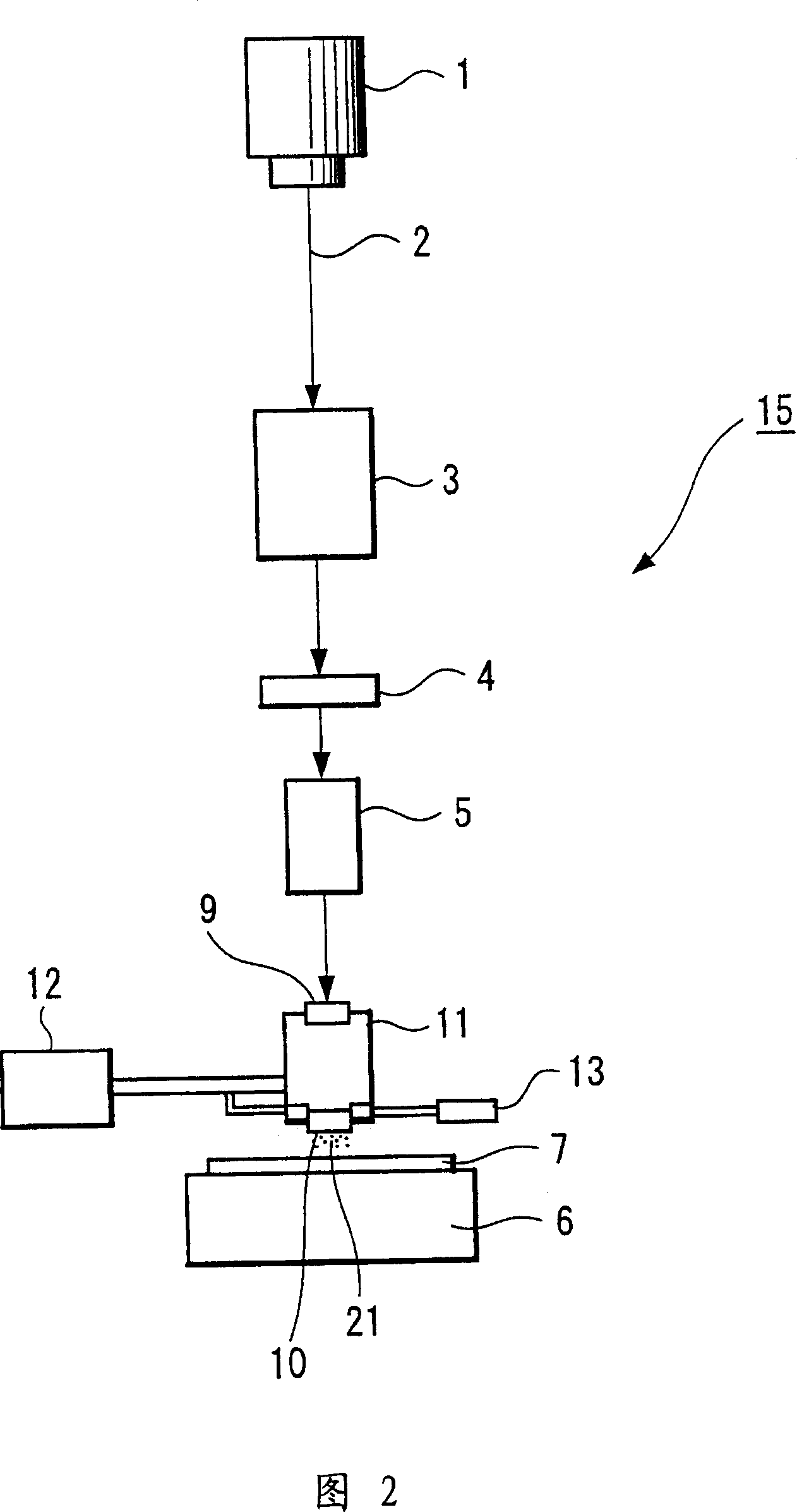
[0033] Hereinafter, the embodiment will be explained with reference to FIGS. 2 to 8 . A laser processing apparatus used in an embodiment includes a laser source, and an optical system that optically projects laser light emitted from the laser source in a predetermined pattern onto a processing surface of a processing object to perform ablation processing on the processing surface.

[0034] FIG. 2 is a diagram schematically showing an example of the configuration of a laser processing apparatus applied to the embodiment. The laser processing device 15 shown in Fig. 2 is configured to have a laser source 1, a beam shaper 3, a mask or an iris 4, a projection lens 5, a processing table 6, a decompression chamber 11 (laser processing head), An outlet portion 12 such as a roughing pump, and a gas inlet portion 13 . The laser processing device 15 performs ablation processing on the processing surface of the processing object 7 using the laser beam emitted by the laser source 1 .

...


PUM


Abstract

A laser processing apparatus is provided. The laser processing apparatus includes a laser processing head having a transmission window, an opening portion, an outlet hole, a first vent hole and a second vent hole. The transmission window transmits laser light by which a processing object is irradiated. The opening portion passes the transmitted laser light to a bottom portion of the laser processing head. The outlet hole discharges an atmosphere in the vicinity of a laser light irradiation region of the processing object to the outside. The first vent hole directs gas into the vicinity of the laser light irradiation region. The second vent hole discharges the atmosphere in the vicinity of the laser light irradiation region. Debris generated from the processing object is discharged from the outlet hole and the second vent hole that are continuous with the opening portion provided at the bottom portion of the laser processing head.

Description

technical field [0001] The present application relates to a technique of performing patterning processing on a transparent conductive film used as a transparent electrode on a multilayer film of an FPD (Flat Panel Display) or the like. In particular, the present application relates to a laser processing device, a laser processing head, and a laser processing method for removing and discharging waste chips based on ablation, thermal melting, Particles and products produced during laser processing of (thermofusion) or a mixture of the two. Background technique [0002] Transparent conductive films are used as transparent electrodes for array substrates (multilayer film substrates) for flat panel displays, solar cells, and the like. Likewise, transparent conductive films are also widely used as transparent electrodes in the field of electronic paper, and the current development of electronic paper has been considered as a future display device and its application has also been...

Claims


Application Information

Patent Timeline
IPC IPC(8): B23K26/14B23K26/06B23K26/08G02F1/1333B23K26/00B23K26/12B23K26/142
CPCB23K26/1458B23K26/1476B23K26/367B23K26/123B23K26/1462B23K26/364B23K26/16B23K26/142H01J9/20H01J11/20H05K1/09
Inventor 阿苏幸成佐佐木良成村瀬英寿山田尚树
Owner SONY CORP
Why Eureka
Try Eureka