
Lever balance head sheave long stroke pumping unit

A lever balance, long-stroke technology, applied to mechanical equipment, belts/chains/gears, mining fluids, etc., can solve problems such as poor transmission reliability, increased manufacturing costs, and complex structures

Inactive Publication Date: 2007-09-12
陈宗武
View PDF0 Cites 5 Cited by
  • Summary
  • Abstract
  • Description
  • Claims
  • Application Information

AI Technical Summary

Problems solved by technology

However, while this machine has significant advantages, there are also some problems to be solved to varying degrees, such as: the extended range part has many moving components, the structure is relatively complicated, and it is subject to large forces, easily damaged, and poor in reliability. and the range-extending mechanism are set on the top of the rack, which makes it difficult to install and maintain on site, and difficult to manufacture and operate.
Secondly, the double crank and double connecting rod structure is easy to form scissors difference, and the connecting rod is long, which requires high material and manufacturing precision of the connecting rod, which brings great difficulty to manufacturing and installation, and increases the weight of the whole machine , increasing the manufacturing cost
Third, the balance system of the machine adopts the free suspension method. Although it has a good balance effect, it also relies on the relative static friction between the sky wheel and the wire rope for transmission. Under heavy load conditions, especially when starting or braking , its transmission reliability is poor, and it is easy to cause fatigue and wear of the wire rope, and the service life is short
Fourth, the balance weight is in the state of free suspension, going up and down at high altitude. When the suspension end of the sucker rod loses load, the balance weight weighing several tons suddenly falls from the height, causing a strong impact on the machine base, and the steel wire rope is greatly thrown. Moving can easily lead to accidents

Method used


Image

  • Lever balance head sheave long stroke pumping unit
  • Lever balance head sheave long stroke pumping unit
  • Lever balance head sheave long stroke pumping unit

Examples


Embodiment Construction

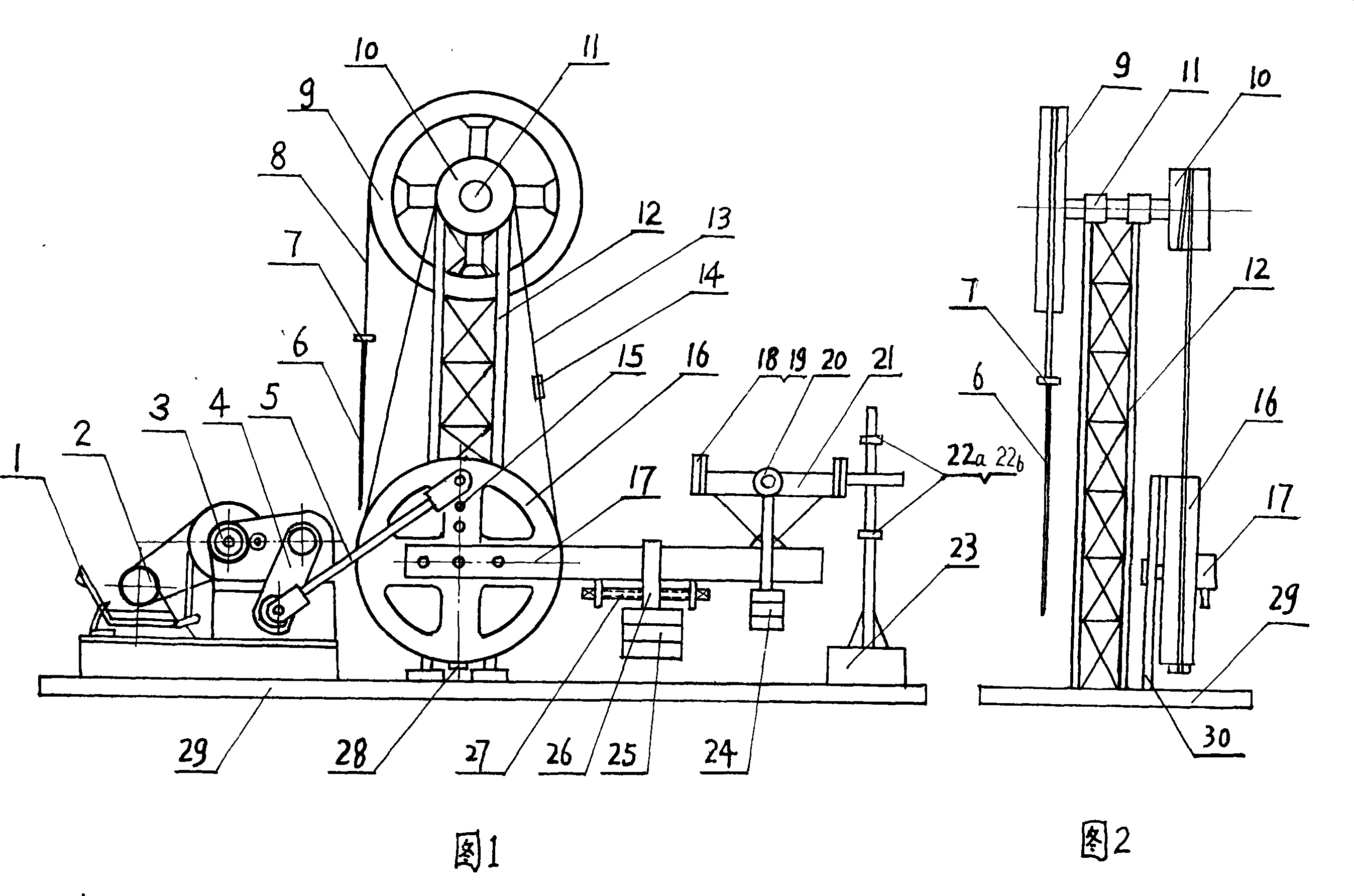
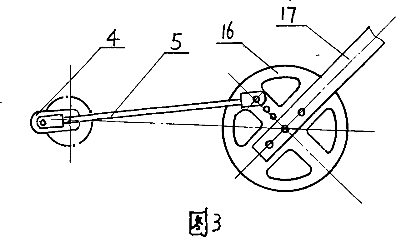
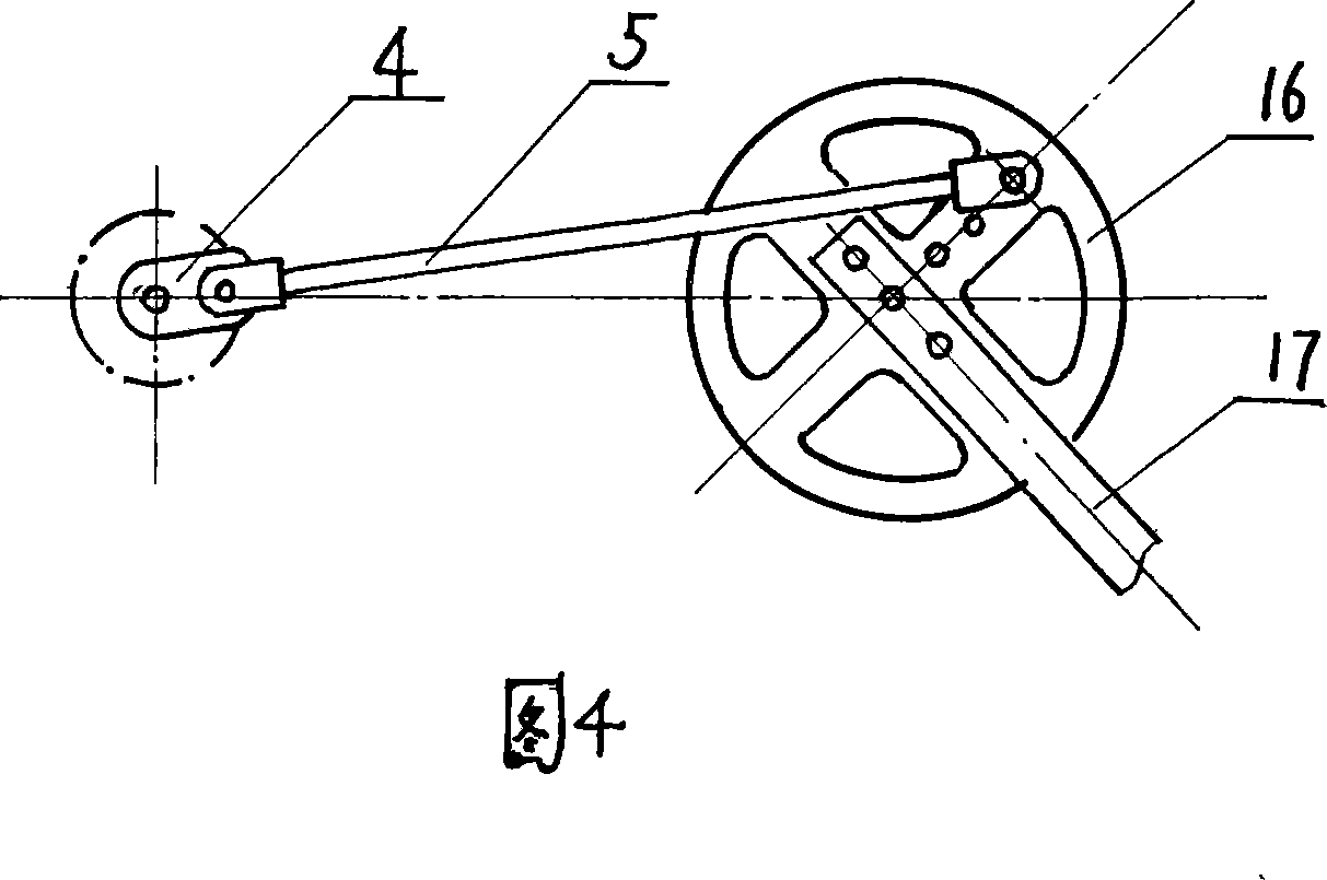
[0015] Referring to Figure 1 and Figure 2, the labels in the figure are: brake mechanism 1, motor 2, reducer 3, crank 4, connecting rod 5, sucker rod 6, rope hanger 7, suspension rope 8, sky wheel 9, Drive wheel 10, central wheel shaft 11, frame 12, steel wire rope 13, rope tightener 14, pin hole 15, drive reversing balance wheel 16, balance bar 17, limit baffle 18, elastic buffer pad 19, roller 20, Slide rail 21, upper limit block 22a, lower limit block 22b, limit bracket 23, auxiliary counterweight 24, counterweight 25, lifting rod 26, balance adjustment part 27, steel rope fixing part 28, base 29, support Seat 30.

[0016] The lever-balanced sky-wheel type long-stroke pumping unit of the present invention adopts a speed-regulating motor 2 for the power part, and is located on one side of the base 29 with the brake mechanism 1 and the speed reducer 3, and the connection and structure of each part still adopt the known technology. I will not repeat them here and there. The ...


PUM


Abstract

The invention relates to a balanced lever sheave-type beam pumping unit with a long stroke for pumping crude oil in oil field. Its characteristics are: it adopts structures of under driving balance wheel extended-range, single-crank connecting rod and balanced lever-type. It connects with the single-crank connecting rod by the driving reversing balance wheel set at bottom of frame. The single-crank connecting rod links one output axis of speed reducer. Central wheel axle is set on top of frame for loading burden sheave and driver. The driver joints to the driving reversing balance wheel through flexible driving medium. The balanced lever-type mechanism is equipped on radial of the driving reversing balance wheel. Compared with the existed technologies, the unit has simple structure, easy realization of long stroke, light weight, less wearing parts, energy saving and convenient equipment and maintenance.

Description

technical field [0001] The invention belongs to the technical field of mechanical oil production equipment, and relates to a lever-balanced sky-wheel type long-stroke pumping unit used for pumping crude oil in an oil field. Background technique [0002] In the known technology, the beam pumping unit usually used in the oil field has its inherent defects due to its structural characteristics, such as bulky, high energy consumption, poor load performance, especially difficult to achieve long stroke. Therefore, long-stroke, low-stroke, large-displacement, and heavy-duty pumping units have always been the research and development direction of oil production equipment at home and abroad. Since the beginning of the 21st century, various beamless pumping units have been developed at home and abroad. Some of the schemes use reversible electric motors or hydraulic motors to drive the drum forward and reverse to realize long-stroke pumping; The stroke of the large beam machine; the r...

Claims


Application Information

Patent Timeline
Patent Type & Authority Applications(China)
IPC IPC(8): E21B43/00F16H37/12
Inventor 陈宗武
Owner 陈宗武
Learn More