
Monofilament metal saw wire

A monofilament type, sawing wire technology, applied in metal sawing equipment, metal processing equipment, sawing machine equipment, etc., can solve the problems of slow and troublesome changes in the outer surface of the sawing wire, and achieve surface quality improvement, long life, and sawing The effect of process stabilization

Active Publication Date: 2007-09-19
ARCELORMITTAL BIESEN & BERTENBERG +1
View PDF1 Cites 32 Cited by
  • Summary
  • Abstract
  • Description
  • Claims
  • Application Information

AI Technical Summary

Problems solved by technology

While these solutions allow for better entrainment of the abrasive, changes to the outer surface of the wire are often slow and cumbersome

Method used


Image

  • Monofilament metal saw wire
  • Monofilament metal saw wire
  • Monofilament metal saw wire

Examples


Embodiment Construction

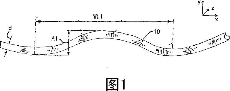
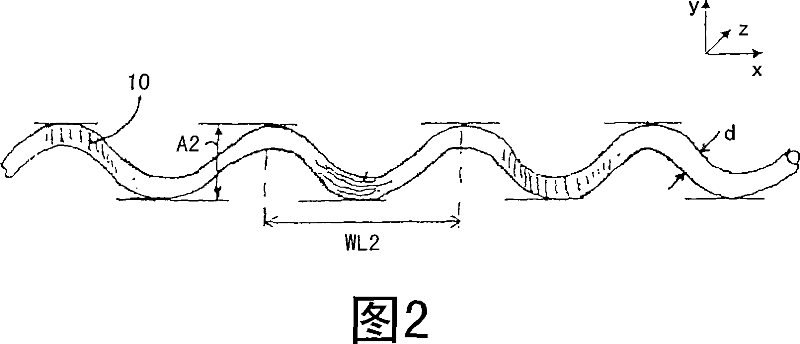
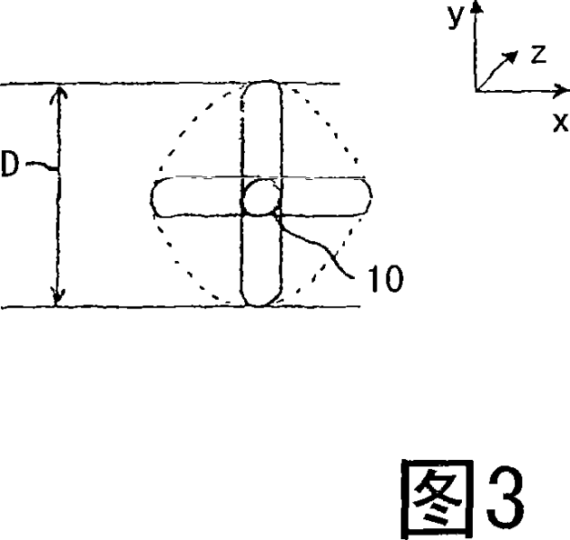
[0033] 1 to 3 illustrate a monofilament type metal sawing wire according to a first embodiment of the present invention. The wire is shown in the x-y plane in FIG. 1 , in the x-z plane in FIG. 2 and in the y-z plane in FIG. 3 . The monofilament type metal sawing wire 10 is provided with a plurality of crimps 12 lying in two different planes. In a first plane, as shown in FIG. 1 , the wire comprises a crimp having a wavelength WL1 and an amplitude A1 . In the second plane, as shown in FIG. 2 , the wire comprises a crimp having a wavelength WL2 and an amplitude A2. Wavelength WL2 is shorter than wavelength WL1, for example, wavelength WL1 may be 5.0 mm, while wavelength WL2 may be about 3.3 mm. The monofilament metal sawing wire 10 itself has a diameter d of 0.25 mm, which remains approximately constant over the entire length of the sawing wire 10 . Preferably, the amplitudes A1 , A2 are 1.10 to 1.30 times the diameter d of the sawing wire 10 . Since the monofilament metal s...


PUM

PropertyMeasurementUnit
wavelengthaaaaaaaaaa
diameteraaaaaaaaaa
diameteraaaaaaaaaa

Abstract

Monofilament metal saw wire for a wire saw, wherein the saw wire being provided with a plurality of crimps. The crimps are arranged in at least two different planes, such that, when measured, between measuring rods of a micrometer, over a length comprising crimps in at least two different planes, a circumscribed enveloping D diameter of the saw wire is between 1.05 and 1.50 times a diameter d of the saw wire itself.

Description

technical field [0001] The present invention relates to monofilament type metal sawing wires, and more particularly to monofilament type metal sawing wires for use with wire saws for sawing hard materials such as blocks of silicon or quartz. Background technique [0002] Wire saws are known for sawing hard materials, such as cutting thin slices from silicon blocks. Such wire saws include monofilament-type metal saw wires that are pulled through the silicon block by moving continuously or back and forth against the silicon block. Monofilament type metal sawing wires are usually coated with abrasives to aid in the sawing process. Shortly after the abrasive is applied to the wire, the wire typically enters the cutting zone where the wire contacts the silicon block. The efficiency of the sawing process depends on several parameters, such as the properties of the hard material block to be cut, the speed of the saw wire, etc. The important factor is the ability of the wire to e...

Claims


Application Information

Patent Timeline
Patent Type & Authority Applications(China)
IPC IPC(8): B23D61/18B24B27/06
CPCB23D61/185B23D57/003B28D1/08B23D61/18B23D57/0007B28D5/045
Inventor 让-皮埃尔·沃布尔格
Owner ARCELORMITTAL BIESEN & BERTENBERG
Learn More