
Piezoelectric oscillator

A piezoelectric oscillator, piezoelectric oscillation technology, applied in power oscillators, electrical components, etc., to achieve the effect of high performance

Inactive Publication Date: 2007-09-19
TOYO TSUSHINKI
View PDF1 Cites 2 Cited by
  • Summary
  • Abstract
  • Description
  • Claims
  • Application Information

AI Technical Summary

Problems solved by technology

[0009] Therefore, the original purpose of obtaining two outputs is to use the post-stage differential amplifier to remove in-phase extraneous noise such as power supply noise of the crystal oscillator. Noise is obviously impossible

Method used

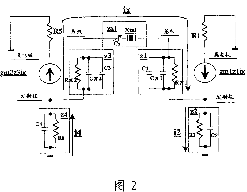
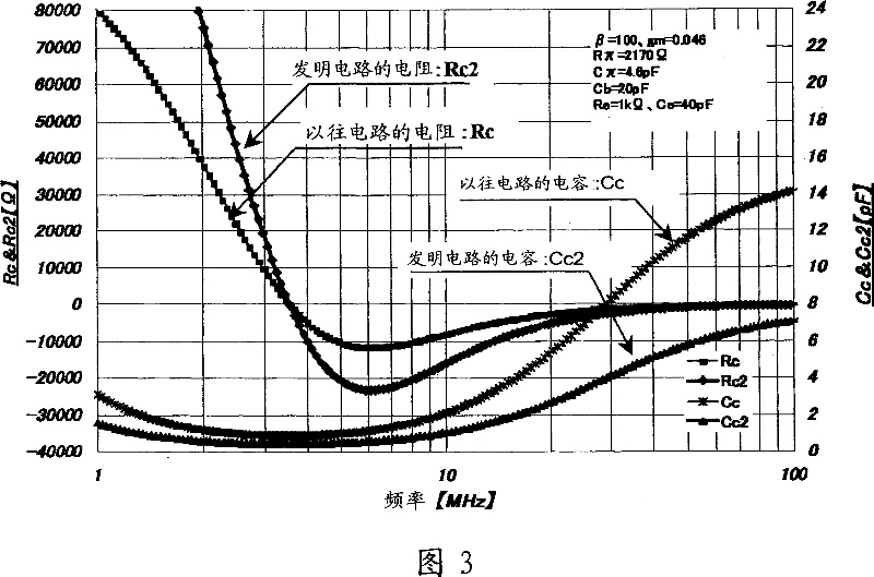

Image

  • Piezoelectric oscillator
  • Piezoelectric oscillator
  • Piezoelectric oscillator

Examples


Embodiment Construction

[0032] Hereinafter, the present invention will be specifically described based on examples.

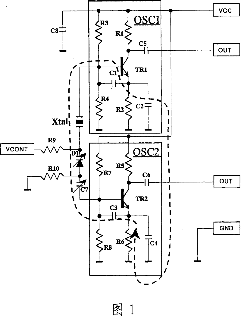
[0033] FIG. 1 is a circuit diagram showing an example of a first embodiment of a voltage-controlled crystal oscillator of the present invention.

[0034] This quartz oscillator has a first oscillation circuit OSC1, a second oscillation circuit OSC2, and a quartz oscillator Xtal.

[0035] Both the first and second oscillation circuits have substantially the same configuration as conventional oscillation circuits (oscillation circuit portions in FIGS. 10 and 11 ) using transistors.

[0036] The crystal oscillator includes a structure in which the input terminal of the first oscillation circuit OSC1 is connected to one terminal of the crystal oscillator Xtal, and a structure in which the other terminal of the crystal oscillator Xtal is connected to the second oscillation circuit OSC2 through a voltage control circuit.

[0037] The voltage control circuit includes: a circuit in which the...


PUM


Abstract

Conventionally, in order to remove in-phase external noise, such as power supply noise and the like, related to a crystal oscillator, one oscillation output is obtained from one oscillator, and then two oscillation outputs, the phases of which are different from each other by 180 degrees, are obtained from that one oscillation output by use of a differential amplifier. However, it was impossible to remove in-phase noise occurring in the oscillator. According to the present invention, a piezoelectric oscillator comprises a piezoelectric vibrator, and first and second oscillator circuits. An input terminal of the first oscillator circuit is connected to one terminal of the piezoelectric vibrator, while an input terminal of the second oscillator circuit is connected to the other terminal of the piezoelectric vibrator. It is arranged that the first and second oscillator circuits provide oscillation outputs whose phases are different from each other by 180 degrees.

Description

technical field [0001] The present invention relates to piezoelectric oscillators, and more particularly to piezoelectric oscillators used in frequency reference generators such as base station devices for fast data communications, measuring instruments, etc., or communication devices such as mobile bodies that require low noise reduction. Background technique [0002] In the piezoelectric controlled crystal oscillator VCXO (Voltage Controlled Xtal OSC) used in fast data communication, etc., in order to achieve low-noise transmission in data transmission, an oscillation circuit that can output two oscillation outputs with a phase difference of 180° is used. . [0003] Fig. 10 shows the prior art. [0004] The oscillating circuit shown in FIG. 10 has a base-grounded amplifier composed of two structures, namely: a structure for inputting one oscillating output from the oscillating circuit to the base of the transistor TR2, and a structure for connecting its emitter to the bas...

Claims


Application Information

Patent Timeline
IPC IPC(8): H03B5/32H03B5/02
CPCH03B5/36H03B2201/0208H03B2202/07
Inventor 佐藤富雄
Owner TOYO TSUSHINKI
Learn More