
Disc shape self-cleaning waste-water thermal energy recoverer

A heat recovery device and disc-type technology, applied in the direction of moving pipe heat exchangers, heat exchanger types, indirect heat exchangers, etc., can solve the problems of difficult removal, increased use costs, and reduced heat exchange efficiency of heat exchangers And other issues

Inactive Publication Date: 2007-09-26
王君健 +1
View PDF0 Cites 9 Cited by
  • Summary
  • Abstract
  • Description
  • Claims
  • Application Information

AI Technical Summary

Problems solved by technology

When the waste water passes through the shell side of the heat exchanger, these impurities will adhere to the surface of the heat exchange tube or the heat exchange plate. The heat exchange efficiency is greatly reduced, and the dirt on the surface of the heat exchange tube or the heat exchange plate is thick and firm, and there are also oil stains, which are difficult to remove. The heat exchange tube or heat exchange plate must be replaced frequently, which greatly improves the user's service life. cost

Method used


Image

  • Disc shape self-cleaning waste-water thermal energy recoverer
  • Disc shape self-cleaning waste-water thermal energy recoverer
  • Disc shape self-cleaning waste-water thermal energy recoverer

Examples


Embodiment Construction

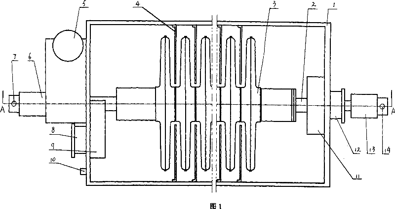
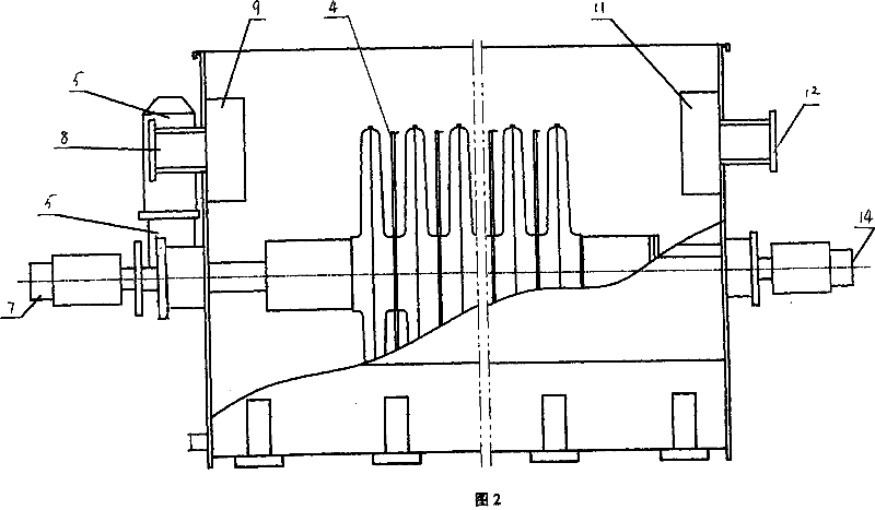
[0015] Referring to Figures 1-2, the disc-type self-cleaning waste water heat recovery device of the present invention is mainly composed of a box body 1, a main shaft 2, a heat exchange plate assembly 3, a deflector plate 4, a power unit 5 and a rotary joint 6.

[0016] The left wall of the box 1 is provided with a waste water inlet 12, and the right side of the waste water inlet 12 is provided with a liquid baffle 11, and the liquid baffle 11 is connected with the inner wall of the left wall of the box 1 to prevent direct impact of waste water The heat exchange plate assembly 3 in the box; the right wall panel of the box body 1 is provided with a waste water outlet 8, and the left side of the waste water outlet 8 is provided with a liquid level control panel 9, and the liquid level control panel 9 is connected with the right wall panel of the box body 1 The inner walls are connected to control the liquid level of the waste water in the tank; the inside of the front and rear w...


PUM


Abstract

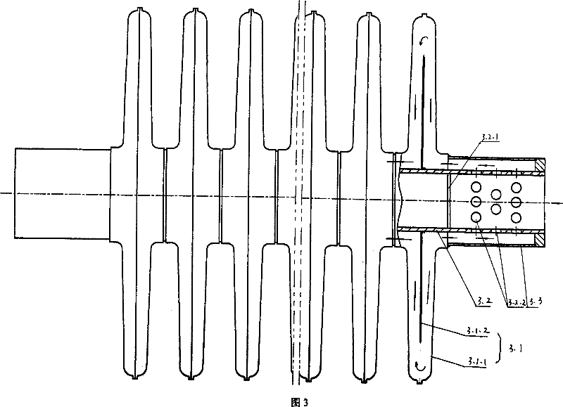
It relates to a round plate self cleaning waste water energy recovery device that comprises the case, main shaft, heat exchanging plate component, guide flow plate and rotating joint, waste water inlet on the case, waste water outlet and guide flow plate, both ends of main shaft connected to rotary joints, clean water inlet and outlet on the rotary joint, heat exchanging plate component cased on the main shaft that comprises the heat plate, inner sleeve tube, heat exchanging plate with several plates in hollow structure, inner sleeve tube both ends having flow resistance baffle plate, several water inlet and outlet holes on the tubular wall, tubular sleeves outside the tube, two tube sleeves inner cavity connected with top and tail two heat exchanging plate, and the rest of the heat exchanging plate interconnected with the heat exchanging plate. It can not make impurities in the waste water stick to the surface of the heat exchanging element to improve heat exchanging efficiency.

Description

technical field [0001] The invention relates to a heat exchange device, in particular to a disc-type self-cleaning waste water heat recovery device. It is mainly used for the recovery and utilization of heat energy in high temperature industrial wastewater produced in the production process of textile, printing and dyeing, papermaking, sugar making, catering and other industries. Background technique [0002] With the rapid development of textile, printing and dyeing, paper making, sugar making, catering and other industries, a large amount of industrial wastewater will be generated in the production process, and the temperature of these wastewater is relatively high, reaching about 80 °C. In order to recycle the heat energy in these wastewaters, most of them use shell-and-tube or plate heat exchangers. Since the moving state of the shell-and-tube or plate-type heat exchange tubes or heat exchange plates is stationary, there is no relative movement with the waste water, and...

Claims


Application Information

Patent Timeline
Patent Type & Authority Applications(China)
IPC IPC(8): F28D11/04
Inventor 王君健巫新强
Owner 王君健
Learn More