Hybrid plasma reactor

A hybrid plasma and plasma technology, applied in the fields of plasma, semiconductor/solid-state device manufacturing, discharge tube, etc., can solve the problems of low PR selectivity, chamber matching, narrow process window, etc.

Inactive Publication Date: 2007-09-26
DMS CO LTD +1
View PDF0 Cites 19 Cited by
  • Summary
  • Abstract
  • Description
  • Claims
  • Application Information

AI Technical Summary

Problems solved by technology

As a result certain phenomena such as etch stop, chamber matching, low PR selectivity, and narrow process window

Method used


Image

  • Hybrid plasma reactor
  • Hybrid plasma reactor
  • Hybrid plasma reactor

Examples


Embodiment Construction

[0032] Exemplary embodiments of the present invention will now be described in more detail with reference to the accompanying drawings. In the following description, detailed descriptions of well-known functions and constructions incorporated herein are omitted for simplicity.

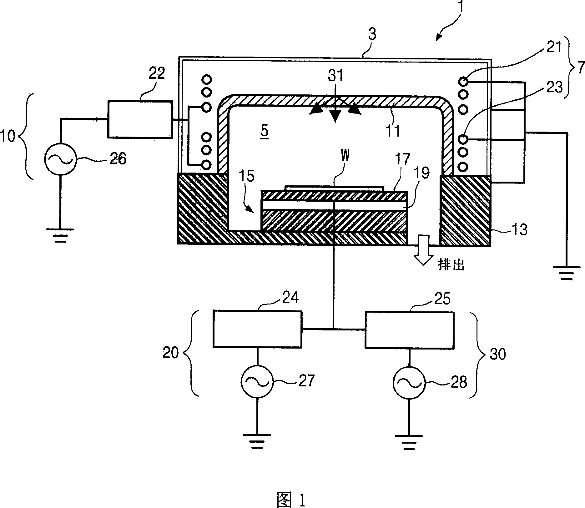
[0033] The present invention provides plasma properties (such as tunable plasma ion density, tunable ion energy distribution, tunable ion energy, tunable radicals, and low Ion-depleting plasma) hybrid type plasma generation apparatus and method. These plasma properties can be controlled using a multi-antenna coil structure, a pillar type dielectric window, an inductively coupled plasma (ICP) source unit provided above the chamber, and a hybrid frequency offset provided to the cathode.

[0034] FIG. 1 shows the configuration of a plasma reactor according to a first exemplary embodiment of the present invention. Referring to FIG. 1 , a plasma reactor includes an inductively coupled plasma (ICP) source ...


PUM


Abstract

Provided is a hybrid plasma reactor. The hybrid plasma reactor includes an ICP (Inductively Coupled Plasma) source unit and a bias RF (Radio Frequency) power supply unit. The ICP source unit includes a chamber, an antenna coil unit, and a source power supply unit. The chamber includes a chamber body whose top is opened and a dielectric window covering the opened top of the chamber body. The antenna coil unit is disposed outside of the dielectric window. The source power supply unit supplies a source power to the antenna coil unit. The bias RF power supply unit supplies a bias RF power to a cathode. The cathode is installed within the chamber and mounts a target wafer on its top.

Description

technical field [0001] The present invention relates to an apparatus used in a semiconductor manufacturing process, and in particular to a plasma reactor. Background technique [0002] Generally, plasma reactors that perform a dry etching process using plasma are classified into a capacitively coupled plasma (CCP) type plasma reactor and an inductively coupled plasma (ICP) depending on a method of generating plasma in a chamber. type plasma reactor. As is known in the art, in a CCP type plasma reactor, the ion flow energy within the plasma chamber increases proportionally as the frequency of the radio frequency (RF) power supplied to the top electrode or cathode decreases. And, in the CCP type plasma reactor, the ion density increases as the frequency of RF power supplied to the upper electrode or the cathode becomes higher. In an ICP type plasma reactor, low ionization conditions and high ionization conditions can be provided within the chamber as the RF power supplied to...

Claims


Application Information

Patent Timeline
Patent Type & Authority Applications(China)
IPC IPC(8): H05H1/24H05H1/02H01L21/3205
CPCH01L21/31116H01J37/32091H01J37/321H01J37/32165H01L21/67069H01L21/02H01L21/3065
Inventor 李元默
Owner DMS CO LTD
Why Eureka
Try Eureka