Combined heat radiating module

A heat dissipation module and composite technology, applied in lighting and heating equipment, cooling/ventilation/heating renovation, cooling machine, etc. The effect of improving design margin, improving quality and saving assembly space

Inactive Publication Date: 2007-09-26
SUNONWEALTH ELECTRIC MACHINE IND
View PDF1 Cites 13 Cited by
  • Summary
  • Abstract
  • Description
  • Claims
  • Application Information

AI Technical Summary

Problems solved by technology

[0004] However, the above-mentioned conventional composite heat dissipation module still has the following disadvantages. The fan unit 96 and the pump unit 97 are separately located at different positions of the first housing 91 and the second housing 92. Therefore, the fan unit 96 and the pump unit 97 It will inevitably take up more assembly space, require a longer circulation path 95, and must be equipped with a motor to perform

Method used


Image

  • Combined heat radiating module
  • Combined heat radiating module
  • Combined heat radiating module

Examples


Embodiment Construction

[0024] In order to have a further understanding and understanding of the purpose of the present invention, technical features and advantages thereof, the number of preferred embodiments of the present invention is cited hereby, and the accompanying drawings are described in detail as follows:

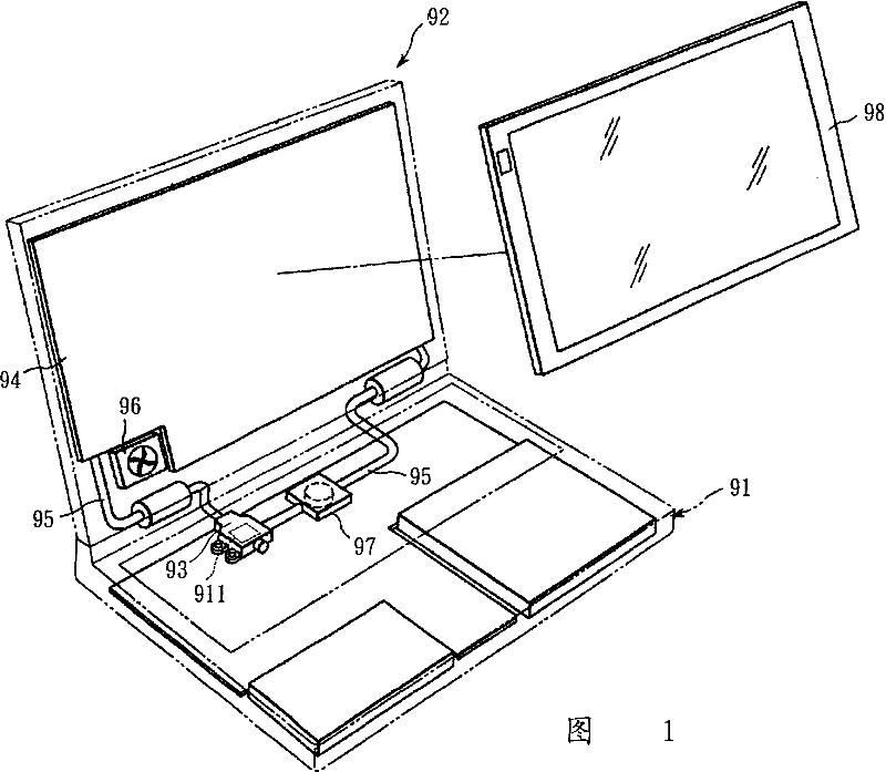
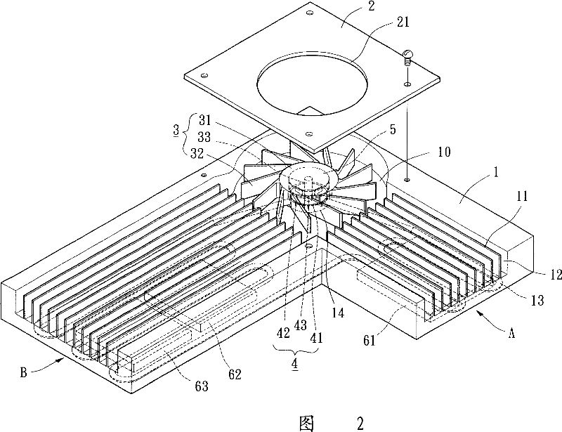
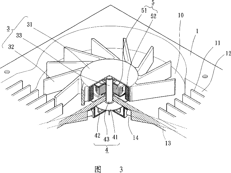
[0025] Please refer to Figures 2 and 3, the first embodiment of the present invention, a composite heat dissipation module, including a heat dissipation plate 1, a cover plate 2, a fan wheel unit 3, a pump unit 4 and at least one power source 5. It is used to perform synchronous or asynchronous air cooling and liquid cooling on at least one object 61 , 62 and 63 to be dissipated. The composite heat dissipation module can be assembled in the casing of a notebook computer, a desktop computer or other electronic devices, and the heat dissipation objects 61, 62 and 63 can be high-power integrated circuits, display panels or electronic components, such as central processing Processor CPU, LC...


PUM


Abstract

The composite-type heat dispersion module comprises: a heat dispersion plate with at least a heat dispersion part and a cycle loop, a turbofan unit near a pump to drive air flow for cooling, and a pump unit to drive liquid along the loop for cooling. Wherein, the heat dispersion part connects turbofan side and at least one target. This invention has function both on air and liquid cooling, saves assembly room and energy consumption, simplifies structure, and benefit to miniaturization of related electronic device.

Description

technical field [0001] The present invention relates to a heat dissipation module, in particular to integrating a fan wheel unit and a pump unit into an adjacent arrangement, which can share the same power source, not only has the double heat dissipation function of air cooling and liquid cooling, saves assembly space, simplifies the structure and reduces The composite heat dissipation module not only has the advantages of energy consumption, but also is conducive to the realization of thinner, thinner and smaller electronic devices to be dissipated. Background technique [0002] Please refer to FIG. 1, the conventional composite heat dissipation module, such as U.S. Publication No. 2004 / 0042173 "Electronic Apparatus Having Circulating Path Through Which Liquid Coolant Cooling Heat" Generating Component Flows)" invention patent, including a first casing 91, a second casing 92, a heat collecting portion 93, a heat dissipation portion 94, a circulation path 95, a fan unit 96 a...

Claims


Application Information

Patent Timeline
IPC IPC(8): H05K7/20H01L23/473G06F1/20F25D16/00
CPCY02B60/1275Y02D10/00
Inventor 洪银树宫原雅晴
Owner SUNONWEALTH ELECTRIC MACHINE IND
Why Eureka
Try Eureka