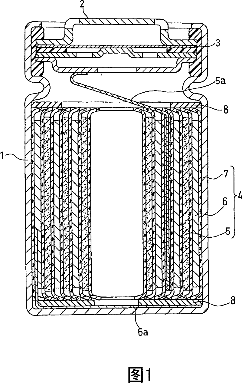
Lithium secondary battery
A lithium secondary battery, porous layer technology, applied in secondary batteries, lithium storage batteries, battery electrodes, etc., can solve problems such as micro-short circuit and reduced Coulombic efficiency, and achieve the effects of improved safety, improved diaphragm strength, and high capacity
- Summary
- Abstract
- Description
- Claims
- Application Information
AI Technical Summary
Problems solved by technology
Method used
Image
Examples
Embodiment 1
[0081] (1) Preparation of negative electrode active material
[0082] 2.5 kg of Ti-Si alloy (mixing weight ratio Ti:Si=37:63) obtained by the melting method and 300 kg of stainless steel balls with a diameter of 1 inch were placed in a vibrating ball mill (available from Chuo Kakohki Industries, Ltd. FV-30) stainless steel container. The container is then covered, which has an internal volume of 95 liters. After the container was evacuated, argon was introduced into the container until it reached 1 atmosphere. Subsequently, the amplitude of the vibrating ball mill was set to 8 mm and the rotation speed of the drive motor was set to 1200 rpm, and mechanical alloying was performed for 72 hours to obtain composite particles a1 containing Ti and Si.
[0083] In addition, Co-Si alloy (Co:Si=41:59), Ni-Si alloy (Ni:Si=41:59), Fe-Si alloy (Fe:Si=39:61) were used under the same conditions. , Ti-Si alloy (Ti:Si=9:91) and Cu-Si alloy (Cu:Si=20:80) to prepare composite particles a2 containin...
Embodiment 1
[0120] Using an 18 μm thick porous polyethylene sheet, a 20 μm thick separator s6 including a laminate of an aramid layer and a polyethylene layer was prepared in the same manner as in Example 1. The content of the aramid layer in the separator s6 is 5 parts by weight per 100 parts by weight of the polyethylene layer. Using the separator s6 and the negative electrode A8, the battery 15 was prepared in the same manner as in Example 1.
Embodiment 2
[0122] An 8 μm thick Si film was formed on each side of the current collector including an 18 μm thick electrolytic copper foil by RF sputtering. In particular, the current collector is fixed to the drum in the vacuum chamber of the RF magnetron sputtering device, and the vacuum chamber is evacuated to 8×10 -4 Pa or less. While introducing argon gas at a flow rate of 50 sccm from the inlet, sputtering was performed. The RF power is 350W.
[0123] Using the negative electrode including the Si thin film thus prepared and the separator s6, the battery 16 was prepared in the same manner as in Example 1.
[0124] Using the negative electrode including the Si thin film thus prepared and the separator s1, the battery 17 was prepared in the same manner as in Example 1.
PUM
| Property | Measurement | Unit |
|---|---|---|
| heat deflection temperature | aaaaa | aaaaa |
| size | aaaaa | aaaaa |
| diameter | aaaaa | aaaaa |
Abstract
Description
Claims
Application Information
 - R&D
- Intellectual Property
- Life Sciences
- Materials
- Tech Scout
- Unparalleled Data Quality
- Higher Quality Content
- 60% Fewer Hallucinations
Browse by: Latest US Patents, China's latest patents, Technical Efficacy Thesaurus, Application Domain, Technology Topic, Popular Technical Reports.
© 2025 PatSnap. All rights reserved.Legal|Privacy policy|Modern Slavery Act Transparency Statement|Sitemap|About US| Contact US: help@patsnap.com

