

Method for producing one-side mould of semi-'u' shaped construction element made of concrete for anti-seepage of channel
A component and lining technology, which is applied in the field of production of anti-seepage lining concrete components for agricultural irrigation and drainage channels, can solve the problems of large number of molds, influence on popularization and use, and high damage rate, so as to improve the overall quality, reduce small accidents on the construction site, The effect of slow demoulding
- Summary
- Abstract
- Description
- Claims
- Application Information
AI Technical Summary
Problems solved by technology
Method used
Image

Examples
Embodiment Construction
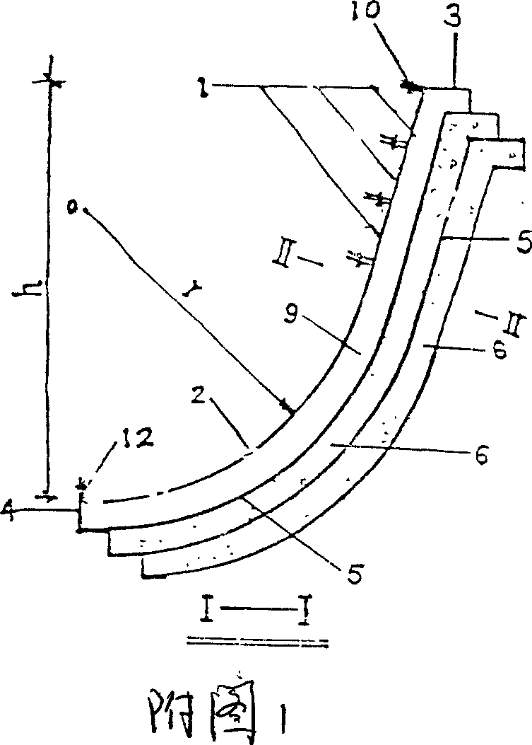
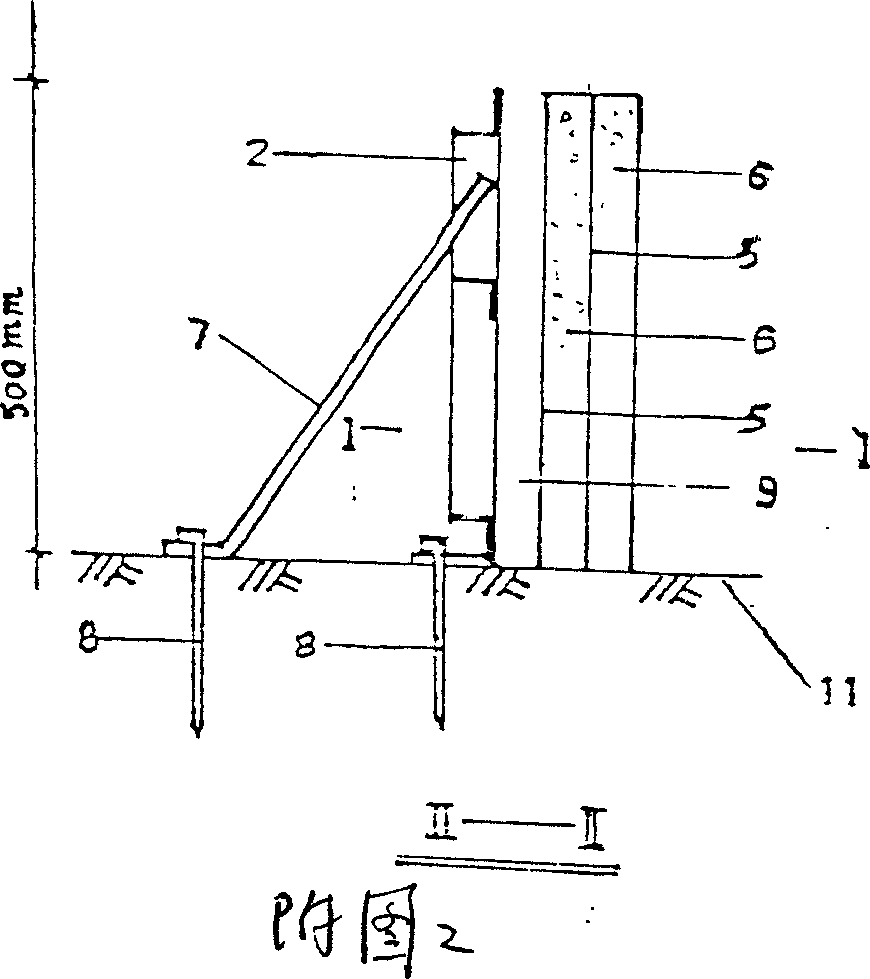
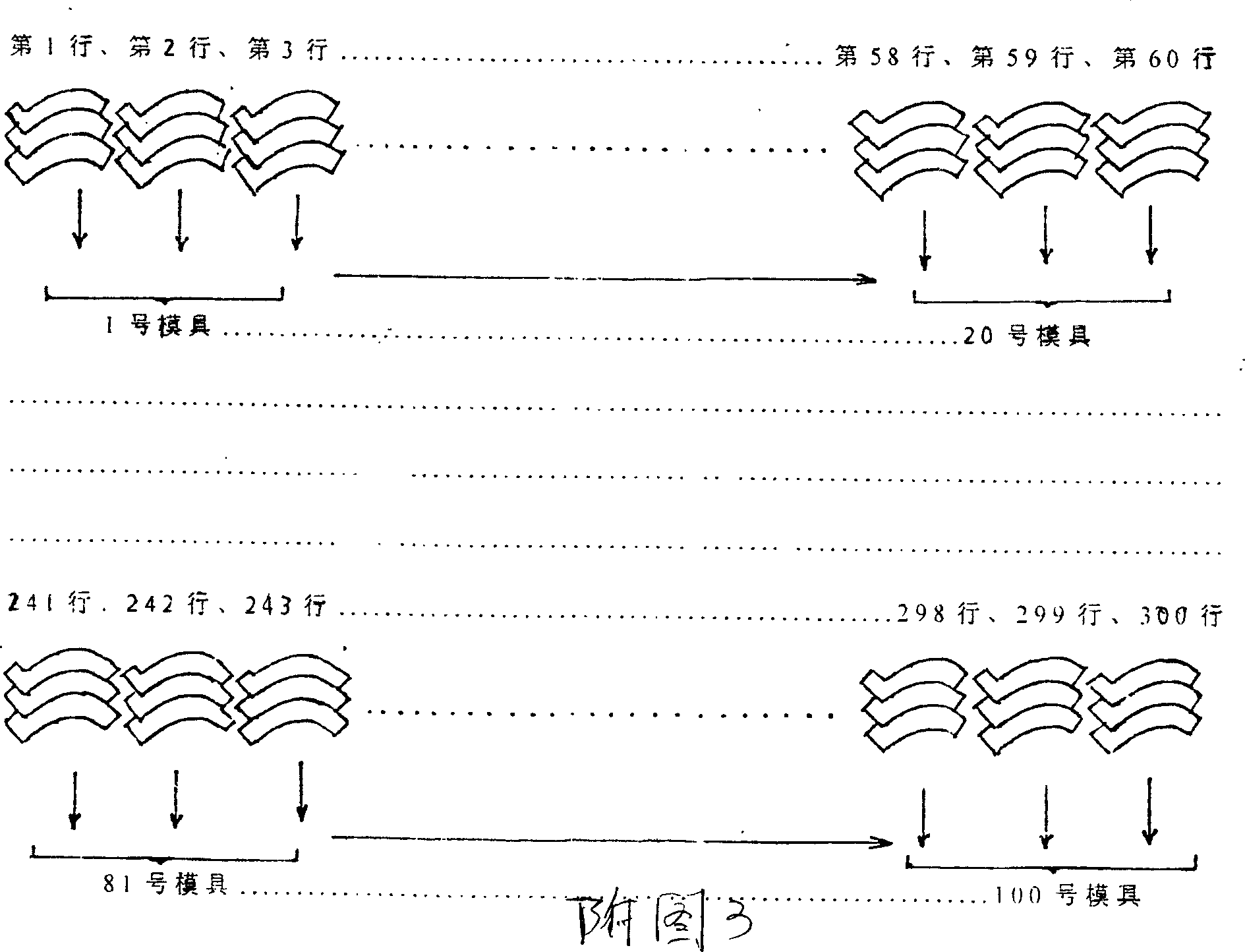
[0017] The method of the present invention can be implemented as long as there are a small amount of shaped steel molds, and the output is determined according to the size of the site. The first semi-U-shaped component is formed by combining two shaped steel molds and can be connected according to the above procedure. Pouring requires skilled processing skills for workers. It mainly refers to concrete mixing, mold assembly and vibrating. The specific production method can be carried out according to the fragmented chain shown in Figure 2.
[0018] Compared with Figure 1 and Figure 2, the lining height of the U-shaped mold is the depth h of the channel, generally 600-900mm, and its arc radius r is in the range of 400-600mm. The elongated part 1 of the template is set in the straight section, and the arc part To shape the mold section 2, there are mold plugs 3 and 4 at both ends of the template. The two plugs can also be made integrally with the template. When chain production is ca...
PUM
 Abstract
Description
Claims
Application Information