Multi-piece part composed of metal element and manufacturing method thereof

A technology of metal components and components, applied in the field of welding equipment, can solve problems such as loss of toughness and embrittlement, achieve low welding internal stress, reliable mutual docking, and prevent aging

Inactive Publication Date: 2007-10-03
STIWA HLDG
View PDF7 Cites 23 Cited by
  • Summary
  • Abstract
  • Description
  • Claims
  • Application Information

AI Technical Summary

Problems solved by technology

The result is a loss of toughness and embritt...

Method used


Image

  • Multi-piece part composed of metal element and manufacturing method thereof
  • Multi-piece part composed of metal element and manufacturing method thereof
  • Multi-piece part composed of metal element and manufacturing method thereof

Examples


Embodiment Construction

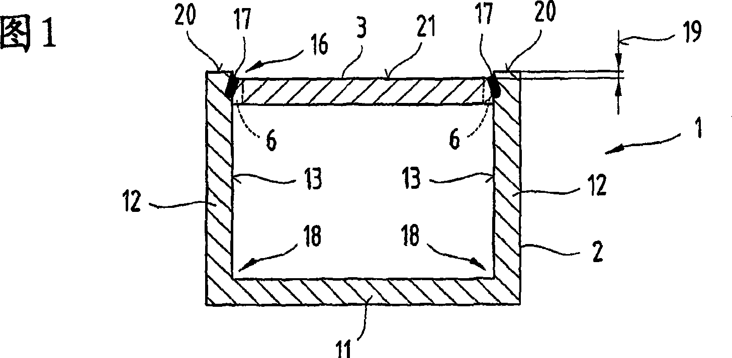
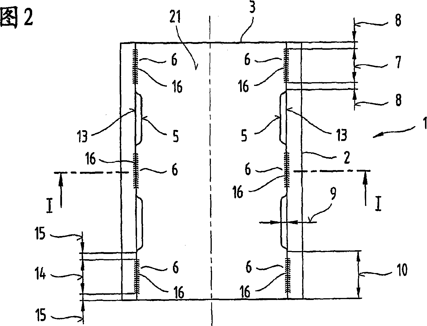
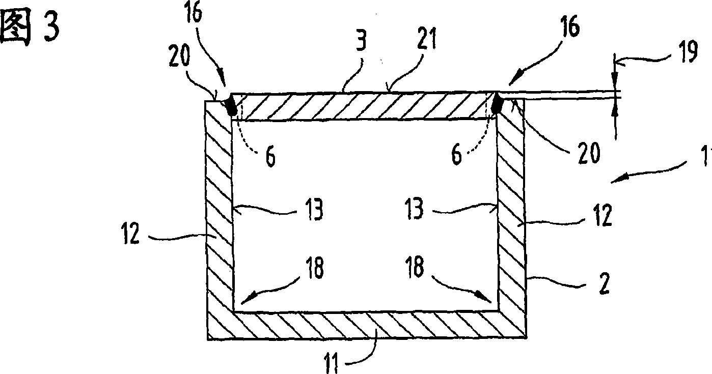
[0069] Firstly, it is provided that the same parts of the different embodiments of the description are provided with the same designation or the same component designation, wherein the disclosure content contained in the entire description can be transferred to the same parts with the same designation or the same component designation . Also selected positional indications in the description, such as top, bottom, side, etc., refer to the directly described and illustrated figure and, when the position is changed, are automatically transferred to the new position. Furthermore, individual features or combinations of features from the various exemplary embodiments shown and described also constitute independent inventions or solutions according to the invention. It should also be pointed out in this connection that only the curved edges forming the deformation region 18 are shown schematically.

[0070] Different views of a first embodiment of the component 1 according to the in...


PUM


Abstract

The invention relates to a subassembly (1) and a method for the production thereof. Said subassembly (1) comprises a first and a second part (2, 3), the first (2, 3) of which is cold-formed. Said parts (2, 3) are provided with parallel planar pieces (20, 21) and contact areas that extend at an angle therefrom in order to place the two parts (2, 3) against each other without leaving a gap therebetween while being joined to each other at the butt joint (16) via a welded seam (17) created by means of beam welding. The planar pieces (20, 21) are disposed so as to be misaligned relative to each other by an offset (19). One of the parts (2, 3) is provided with a contacting projection (6) which embodies the contact area of the first part (2). The parts (2, 3) are positioned relative to each other in such a way that the second part (3) forms the butt joint (16) along with the first part (2) in the section of the first part (2) in which an offset thickness of the basic material is smaller than the offset thickness of the structure in a deformation zone (18) created on the first part (2) by cold forming.

Description

technical field [0001] The invention relates to a component comprising at least two metal elements connected to each other by means of beam welding, a method for its manufacture and a welding device, as in claims 1, 2, 11, 41 and 49 described in the preamble. Background technique [0002] From DE 196 36 212 C1 and DE 199 48 013 A1 it is known that two sheet metal parts of different thicknesses are produced by butt-butting their mutual edges to be welded together by means of beam welding, in particular laser beam welding. The welded seams are connected to each other along the abutment formed by the edges abutting against each other substantially without gaps. The sheet metal parts welded together serve as so-called deep-drawn sheet blanks, which are formed in a subsequent deep-drawing step, for example, into a body panel with regions of different thickness. In order to achieve problem-free and tool-safe behavior in the forming tool during the subsequent deep drawing of such...

Claims


Application Information

Patent Timeline
IPC IPC(8): B23K33/00B23K26/24B23K26/26
CPCB23K26/243Y10T428/12347B23K33/00B23K26/26B23K26/242
Inventor M·比藤多尔费尔R·海姆尔
Owner STIWA HLDG
Why Eureka
Try Eureka