W-shape flame boiler for preventing side wall water cooling wall slagging scorification

A water-cooled wall and side wall technology, applied in steam boilers, combustion methods, combustion chambers, etc., can solve problems such as incomplete combustion, flame prolongation, and accelerated slagging on the heating surface

Active Publication Date: 2007-10-10
HARBIN INST OF TECH
View PDF0 Cites 32 Cited by
  • Summary
  • Abstract
  • Description
  • Claims
  • Application Information

AI Technical Summary

Problems solved by technology

[0003] The purpose of the present invention is to solve the problem that in the existing W-shaped flame boiler, its water-cooled wall (wing wall) is composed of water-cooled wall tubes and fins tightly connected, and the gas composition near the water-cooled wall is difficult to burn because of anthracite and lean coal. Incomplete combustion and flame pro

Method used


Image

  • W-shape flame boiler for preventing side wall water cooling wall slagging scorification
  • W-shape flame boiler for preventing side wall water cooling wall slagging scorification
  • W-shape flame boiler for preventing side wall water cooling wall slagging scorification

Examples


specific Embodiment approach 1

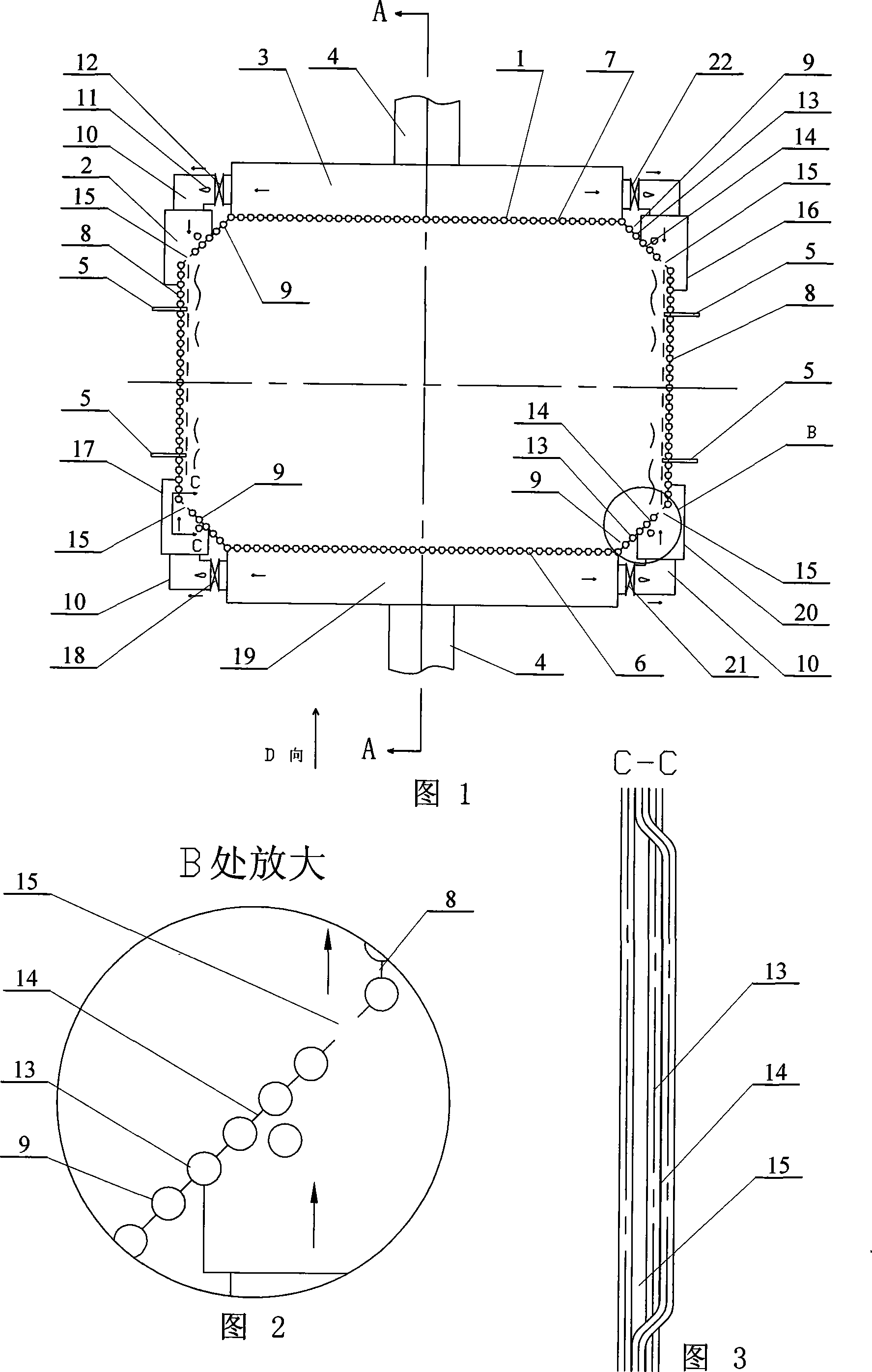
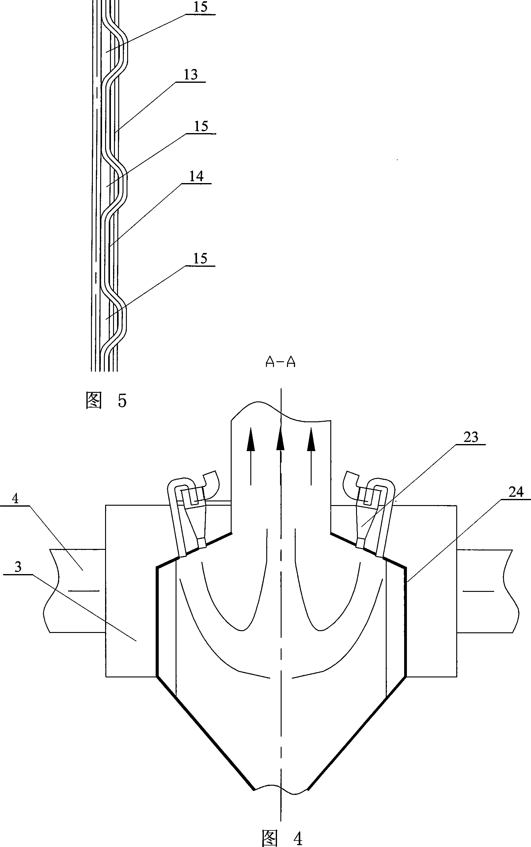
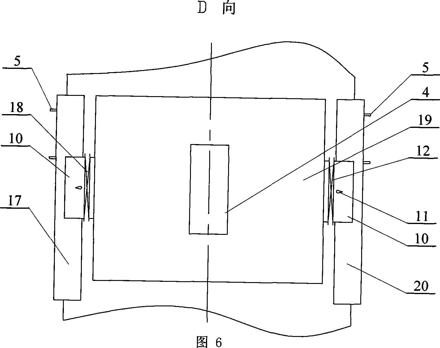
[0005] Specific embodiment one: (refer to Fig. 1~Fig. 4, Fig. 6) this embodiment consists of a furnace body 1, a first wall-attached air box 2, a first main air box 3, two secondary air ducts 4, four wall-attached Wind duct 10, the second wall-attached wind box 16, the third wall-attached wind box 20, the fourth wall-attached wind box 17 and the second main wind box 19, the body of furnace 1 is composed of front wall 6, rear wall 7, Composed of two side walls 8 and four wing walls (water-cooled walls) 9, the front wall 6, the rear wall 7 and the side walls 8 are arranged in a quadrangular shape, between the two side walls 8 and the front wall 6, the two side walls 8 It is connected with the rear wall 7 by the wing wall 9, and the wing wall 9 is composed of the water-cooled wall tube 13 and the fin 14; the first wall-mounted wind box 2, the second wall-mounted wind box 16, the third The wall-attached wind box 20 and the fourth wall-attached wind box 17 are respectively arranged...

specific Embodiment approach 2

[0006] Embodiment 2: (see FIG. 1 ) The difference between this embodiment and Embodiment 1 is that each wall-attached air duct 10 is provided with a damper 11 . Play the purpose of controlling wind flow. Other compositions and connections are the same as in the first embodiment.

specific Embodiment approach 3

[0007] Specific embodiment three: (referring to Fig. 1) the difference between this embodiment and specific embodiment two is that it increases the first speed detector 12, the second speed detector 22, the third speed detector 21 and the fourth speed detector 18, the first speed detector A speed detector 12 is arranged between the first wall-attached wind box 2 and one end of the first main wind box 3, and a second speed detector 22 is arranged between the second wall-attached wind box 16 and the other end of the first main wind box 3, The third speed detector 21 is arranged between the third wind box 20 and one end of the second main wind box 19, and the fourth speed detector 18 is arranged between the fourth wind box 17 and the other end of the second main wind box 19. . The first speed detector 12, the second speed detector 22, the third speed detector 21 and the fourth speed detector 18 added in this embodiment are used to monitor the flow velocity of the wind in each wal...


PUM


Abstract

A W type of flame boiler enabling to prevent water-cooled wall of wing walls from slagging scarification is prepared for setting four wall-wind fans separately on external sides of four wing walls and arranging ventilation gap on each of four wing walls.

Description

technical field [0001] The invention relates to a W-shaped flame boiler. Background technique [0002] With the development of the electric power industry, in order to burn anthracite, lean coal and other low volatile coals, W-flame boilers have been used more and more, but W-flame boilers generally have side wall water wall slagging during operation. question. Slagging refers to the process of ash accumulation on the heated wall surface. Slagging is not only a complex physical and chemical process, but also a very complex hydrodynamic process. For W-type flame boilers burning low-volatile coal such as anthracite and lean coal, slagging is mainly the result of the combined effects of the following three factors: 1. The influence of coal quality characteristics. For coals with low ash melting point, if the temperature in the central area of ​​the flame is high, the ash particles are easy to soften or melt and adhere to the heating surface to cause slagging. 2. High furnace...

Claims


Application Information

Patent Timeline
IPC IPC(8): F23C3/00F22B31/00
Inventor 李争起任枫陈智超孙亮刘辉
Owner HARBIN INST OF TECH
Why Eureka
Try Eureka