
Optical sensor and its electronic equipment

A technology of optical sensing and light sensing, which is applied in the direction of electrical digital data processing, instrumentation, and input/output process of data processing, etc. It can solve the problems of lack, failure to output, and reduce the sensing performance of optical sensors, etc.

Inactive Publication Date: 2007-10-10
BENQ CORP
View PDF0 Cites 0 Cited by
  • Summary
  • Abstract
  • Description
  • Claims
  • Application Information

AI Technical Summary

Problems solved by technology

[0004] Therefore, when the relative moving speed between the object and the optical sensing device 10 is extremely fast (greater than 100f) or extremely slow (less than f), the differentiator 4 cannot output The differential signal d1 corresponding to the sensing signal frequency (greater than 100f or less than f), thus affecting the computer 6 when processing the data signal D1 lacks data outside the corresponding (f, 100f) signal frequency range, making the display on the Cursor can not produce corresponding very fast or slow movement
greatly reduce the sensing performance of the optical sensor 10

Method used


Image

  • Optical sensor and its electronic equipment
  • Optical sensor and its electronic equipment
  • Optical sensor and its electronic equipment

Examples


Embodiment 1

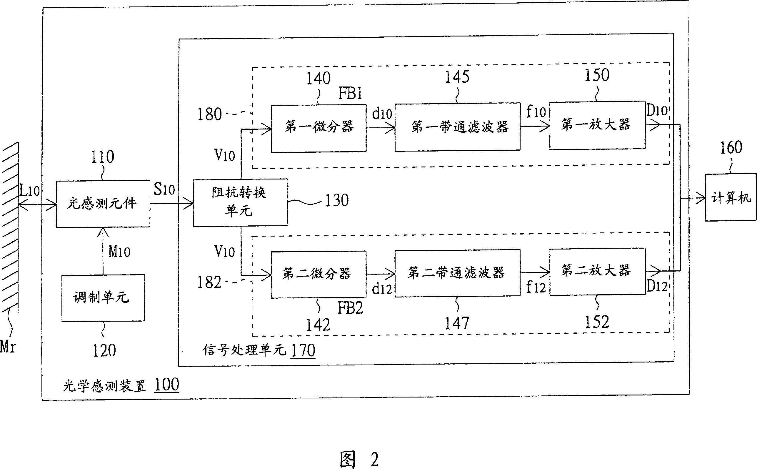
[0034] Please refer to FIG. 2 , which shows a structural block diagram of an optical sensing device connected to a computer according to a first embodiment of the present invention. The optical sensing device 100 is, for example, an optical mouse for sensing a relatively moving object Mr. The optical sensing device 100 includes a light sensing component 110 , a modulation unit 120 and a signal processing unit 170 . The photo-sensing component 110 uses a laser diode to send a laser signal L10 to the object Mr according to the modulation signal M10 (such as a triangular wave signal) output by the modulation unit 120, and uses the photodiode to receive the laser light L10 reflected from the object Mr, so as to output the sensing signal. Signal S10. The signal processing unit 170 is coupled to the photo-sensing component 110 for signal processing the sensing signal S10 and outputting the first data signal D10 and the second data signal D12 accordingly. The frequencies of the fir...

Embodiment 2

[0040] Please refer to FIG. 3 , which shows a structural block diagram of an optical sensing device connected to a computer according to a second embodiment of the present invention. The main difference between the optical sensing device 300 of this embodiment and the optical sensing device 100 of Embodiment 1 is that the signal processing unit 370 of this embodiment also includes a time division multiplexing (timedivision multiplexing, TDM) encoder 310 and a TDM translator. Encoder 320. The TDM encoder 310 is coupled between the impedance conversion unit 130 and the first differentiation unit 180 and the second differentiation unit 182 , and the TDM decoder 320 is coupled after the first differentiation unit 180 and the second differentiation unit 182 . In addition, the modulation unit 120 outputs a first frequency modulation signal M20 and a second frequency modulation signal M22 , wherein the first frequency is, for example, 100 Hz, and the second frequency is, for example,...


PUM


Abstract

An optical sensing device is prepared for using light sensing component to sense object according to modulation signal and outputting sensed signal, coupling signal processing unit with light sending component in order to process sensed signal and to output the first and the second data signals, containing frequency of the first data signal in the first frequency range of sensed signal, containing frequency of the second data signal in the second frequency range of sensed signal and making the first frequency range be not equal to the second one.

Description

technical field [0001] The present invention relates to an optical sensing device and its electronic equipment, in particular to an optical sensing device and its electronic equipment capable of separately processing moving object sensing signals in two or more different frequency bands. Background technique [0002] An optical sensing device that utilizes the physical phenomenon of laser self-mixing to sense the moving position of an object has been widely used in different fields, such as an optical mouse of a computer system. Please refer to FIG. 1 , which shows a schematic block diagram of a connection between a traditional optical sensing device and a computer. The optical sensing device 10 , such as an optical mouse, includes a light sensing component 1 , a modulation unit 2 , an impedance conversion unit 3 , a differentiator 4 and an amplifier 5 . The light sensing element 1 includes a laser diode (laserdiode) and a photodiode (photo diode) (not shown in the figure)....

Claims


Application Information

Patent Timeline
IPC IPC(8): G06F3/033G06F3/0354
Inventor 邱奕铭马国栋
Owner BENQ CORP
Features
  • Generate Ideas
  • Intellectual Property
  • Life Sciences
  • Materials
  • Tech Scout
  • Unparalleled Data Quality
  • Higher Quality Content
  • 60% Fewer Hallucinations
Learn More