
Laser module

A technology of laser and laser source, applied in the field of laser source, can solve the problems of increasing volume and complicating system

Inactive Publication Date: 2007-10-10
SAMSUNG ELECTRONICS CO LTD
View PDF1 Cites 1 Cited by
  • Summary
  • Abstract
  • Description
  • Claims
  • Application Information

AI Technical Summary

Problems solved by technology

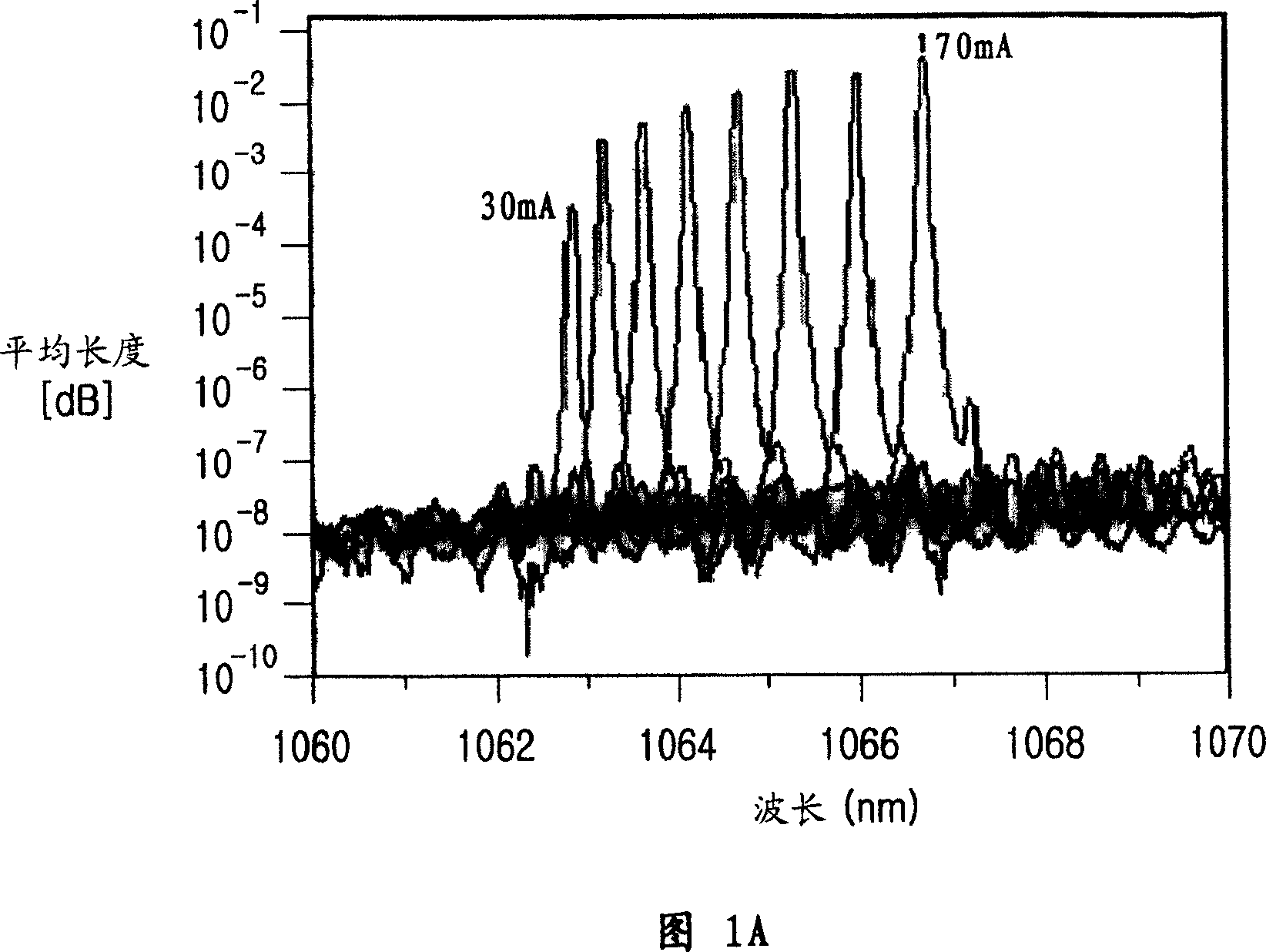
Therefore, the volume of the conventional laser module increases and causes system complexity

Method used


Image

  • Laser module
  • Laser module
  • Laser module

Examples


Embodiment Construction

[0018] Hereinafter, embodiments of the present invention will be described in detail with reference to the accompanying drawings. For the purpose of clarity and simplicity, detailed descriptions of known functions and constructions incorporated herein are omitted so as not to obscure the subject matter of the present invention.

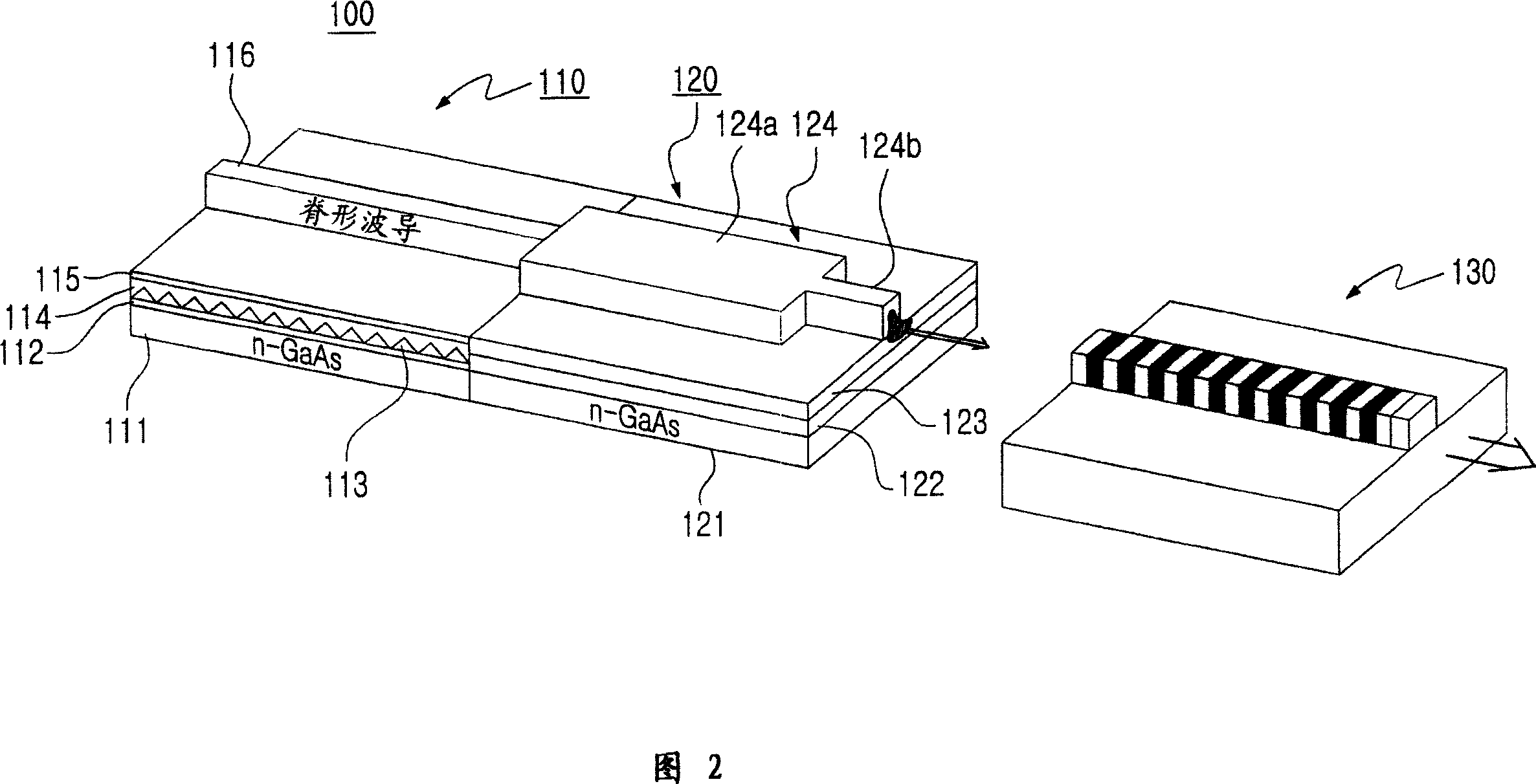
[0019] FIG. 2 is a view illustrating a laser module for generating green laser light in which there is no wavelength shift caused by direct modulation according to an embodiment of the present invention. Referring to FIG. 2, the laser module 100 according to the present invention includes: a laser source 110 for generating the first light; a nonlinear crystal 130 for second harmonic oscillation for wavelength conversion from the first light to the second light; The multimode interferometer 120 is located between the laser source 110 and the nonlinear crystal 130 .

[0020] The laser source 110 and the multimode interferometer 120 are preferably forme...


PUM

PropertyMeasurementUnit
wavelengthaaaaaaaaaa

Abstract

Disclosed is a laser module for generating laser light without a wavelength shift during a direct modulation of high frequency. The laser module includes: a laser light source for generating a first light; a nonlinear crystal for secondary harmonic generation for wavelength-converting the first light into a second light; and a multi-mode interferometer placed between the laser light source and the secondary harmonic generation, for modulating the intensity of the first light.

Description

technical field [0001] The present invention relates to a laser source, and more particularly to a laser source comprising a multimode interferometer and a nonlinear crystal for second harmonic oscillation, in which there is no wavelength shift. Background technique [0002] Various devices for providing image information have been developed, such as cathode ray tubes, liquid crystal displays, plasma displays, and the like. In addition, laser scanning type image devices and projection type image devices have been developed and commercialized to generate images using laser light. The laser scanning type image device and the projection type image device include: a laser source for generating three primary colors of red, green and blue; an optical engine; and a spatial light modulator for generating image information from an incident light source. [0003] Since semiconductor green laser diodes have not been used until recently, it is not possible to ...

Claims


Application Information

Patent Timeline
Patent Type & Authority Applications(China)
IPC IPC(8): H01S5/00G02F1/35H01S5/12
CPCH01S5/0265G02F1/37H01S5/0092H01S5/1014H01S5/12H01S5/22H01S5/026
Inventor 朴炳勋沈钟仁
Owner SAMSUNG ELECTRONICS CO LTD
Learn More