Second harmonic oscillator

a second harmonic oscillator and harmonic technology, applied in oscillator generators, instruments, measurement devices, etc., can solve the problems of deterioration of phase noise, high output power, and most approaches to improve output power, so as to improve output power and improve phase noise.

Inactive Publication Date: 2009-12-08
MITSUBISHI ELECTRIC CORP
View PDF30 Cites 1 Cited by
  • Summary
  • Abstract
  • Description
  • Claims
  • Application Information

AI Technical Summary

Benefits of technology

[0012]The present invention has been made to solve the above problem, and therefore an object of the present invention is to provide a second harmonic oscillator which is capable of improving the output power without substantially changing the physical size of the entire circuit and without deteriorating the phase noise.
[0014]The second harmonic oscillator according to the present invention is capable of improving the output power without substantially changing the physical size of the entire circuit and without deteriorating the phase noise.

Problems solved by technology

In addition, in recent years, it is also required that the output power be high in addition to the low phase noise.
In the case where the physical size of the oscillator is fixed, most approaches to improve the output power deteriorate the phase noise.

Method used


Image

  • Second harmonic oscillator
  • Second harmonic oscillator
  • Second harmonic oscillator

Examples


first embodiment

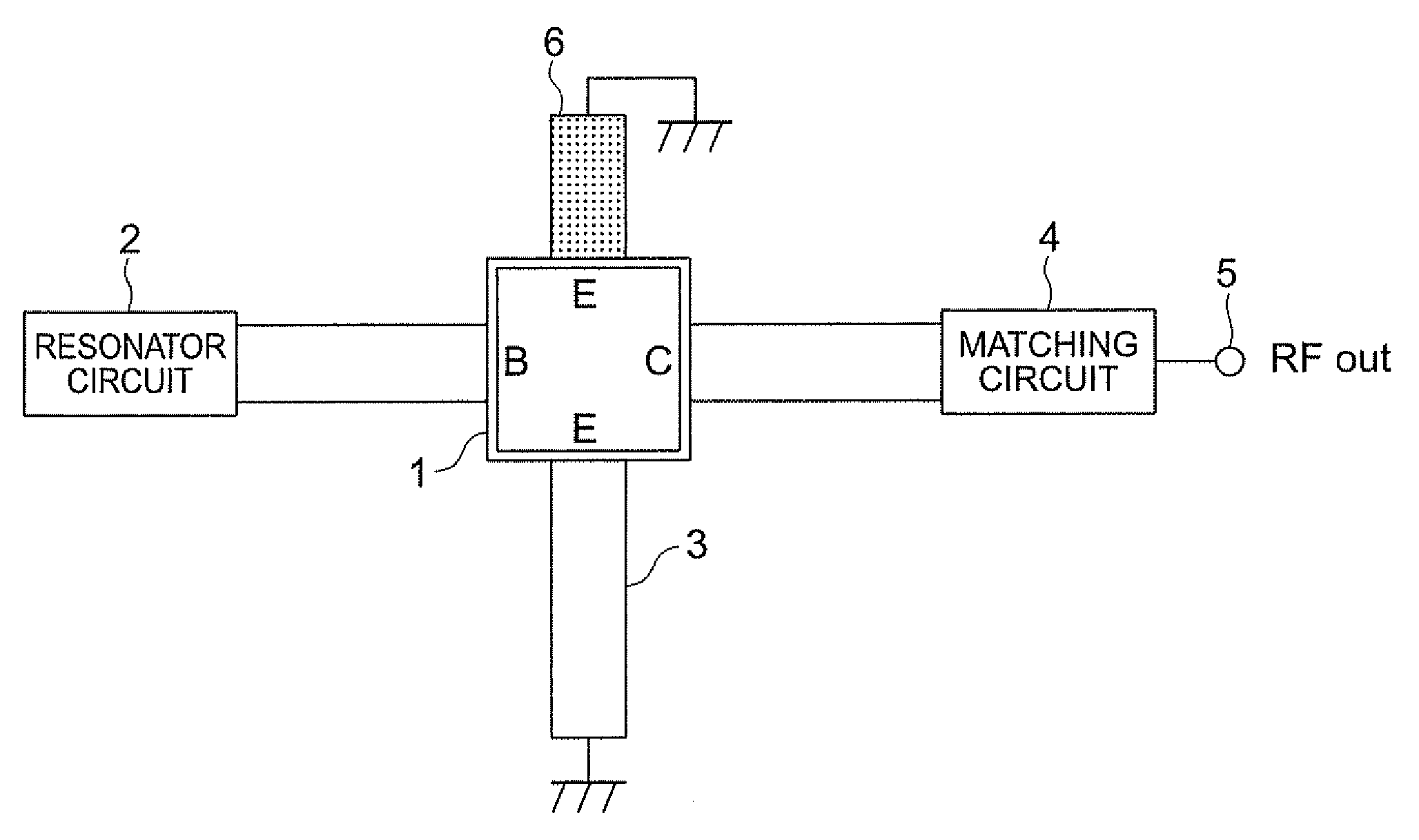
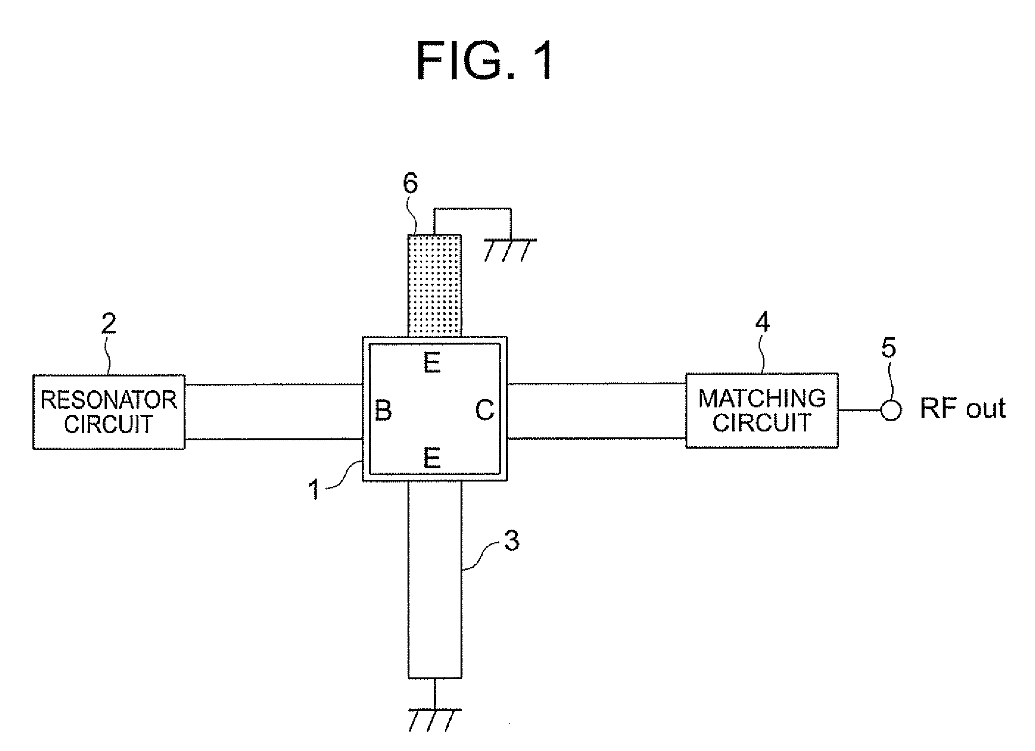
[0022]A second harmonic oscillator according to a first embodiment of the present invention will be described with reference to FIGS. 1 to 4. FIG. 1 is a diagram showing the configuration of the second harmonic oscillator according to the first embodiment of the present invention. In the respective drawings, the same symbols represent identical or corresponding parts.

[0023]Referring to FIG. 1, the second harmonic oscillator according to the first embodiment of the present invention is of a series positive feedback configuration, which includes a transistor 1 having two emitter terminals (E), a resonator circuit 2, a ground circuit 3, a matching circuit 4, an output terminal 5 of a signal, and a λ / 4 short-circuiting stab 6.

[0024]In the case where the transistor 1 is a field effect transistor (FET), the emitter terminals (E), a base terminal (B), and a collector terminal (C) are replaced with a source terminal, a gate terminal, and a drain terminal, respectively.

[0025]The resonator ci...

second embodiment

[0048]Description will be made of a second harmonic oscillator according to a second embodiment of the present invention.

[0049]In the above first embodiment of the present invention, the λ / 4 short-circuiting stab 6 that is open with respect to the fundamental harmonic signal has been described. Alternatively, it is possible to connect the microwave line short-circuiting stab that is not open with respect to the fundamental harmonic signal. In this case, it is necessary to redesign the load impedances of the fundamental harmonic signal of the ground circuit 3. For example, the length of the ground circuit 3 is changed.


PUM


Abstract

A second harmonic oscillator has a series positive feedback configuration, suppresses output of a fundamental signal, and outputs a second harmonic signal having a frequency in a range from 1 GHz to 200 GHz generated inside of a circuit. The second harmonic oscillator includes: a transistor having a base terminal, a first emitter terminal, a second emitter terminal, and a collector terminal; a resonator circuit connected to the base terminal; a first transmission line shod-circuiting stub connected to one of the two emitter terminals; and a second transmission line short-circuiting stub connected to the other of the two emitter terminals and having a line length obtained by adding one-fourth of one wavelength of the fundamental signal to an integer multiple of one-half wavelength of the fundamental signal.

Description

BACKGROUND OF THE INVENTION[0001]1. Field of the Invention[0002]The present invention relates to a second harmonic oscillator that operates mainly in a microwave or millimeter wave domain.[0003]2. Description of the Related Art[0004]Along with the widespread of consumer radars such as an on-vehicle radar and a cellular phone, a demand for downsizing an oscillator whose output frequency exceeds 1 GHz and enhancing the performance of the oscillator has been increased. The “oscillator” refers to a circuit that oscillates an electric signal in the interior of the circuit and transmits the electric signal to the external.[0005]In a fundamental harmonic oscillator, in a case where an electric signal having a desired frequency is generated with excellent characteristics (high output, low phase noise), it is necessary for a transistor to have a sufficient gain at the desired frequency. However, the gain of the transistor generally decreases as the frequency becomes higher. Therefore, the ha...

Claims


Application Information

Patent Timeline
Patent Type & Authority Patents(United States)
IPC IPC(8): H03B1/00
CPCH03B19/14
Inventor WATANABE, SHINSUKEINOUE, AKIRA
Owner MITSUBISHI ELECTRIC CORP
Why Eureka
Try Eureka