Filter with fiber filter element rotary displacement

A rotary displacement and filter technology, applied in the direction of loose filter material filter, gravity filter, filtration and separation, etc., can solve the problem that the fiber bundle cannot be compacted and stretched loosely, and the fiber porosity cannot be adjusted. High-precision water quality, filtration Large resistance and other problems, to achieve the effect of long filtration cycle, simple structure and high filtration accuracy

Inactive Publication Date: 2007-10-17
NORTHEAST DIANLI UNIVERSITY
View PDF0 Cites 10 Cited by
  • Summary
  • Abstract
  • Description
  • Claims
  • Application Information

AI Technical Summary

Problems solved by technology

[0002] The existing fiber filter has a structure in which several fiber bundles are evenly distributed between the fixed orifice plate and the moving orifice plate, and the porosity of the fibers is adjusted by squeezing the moving orifice plate in the axial direction by the natural momentum of water inflow and outflow. The disadvantage is that several fiber bundles of the fiber filter element cannot be compacted or completely stretched and loosened, and the purpose of adjusting the porosity of the fibers and the requirements of high-precision water quality cannot be achieved, and the filtration resistance is large.

Method used


Image

  • Filter with fiber filter element rotary displacement
  • Filter with fiber filter element rotary displacement
  • Filter with fiber filter element rotary displacement

Examples


Embodiment 1

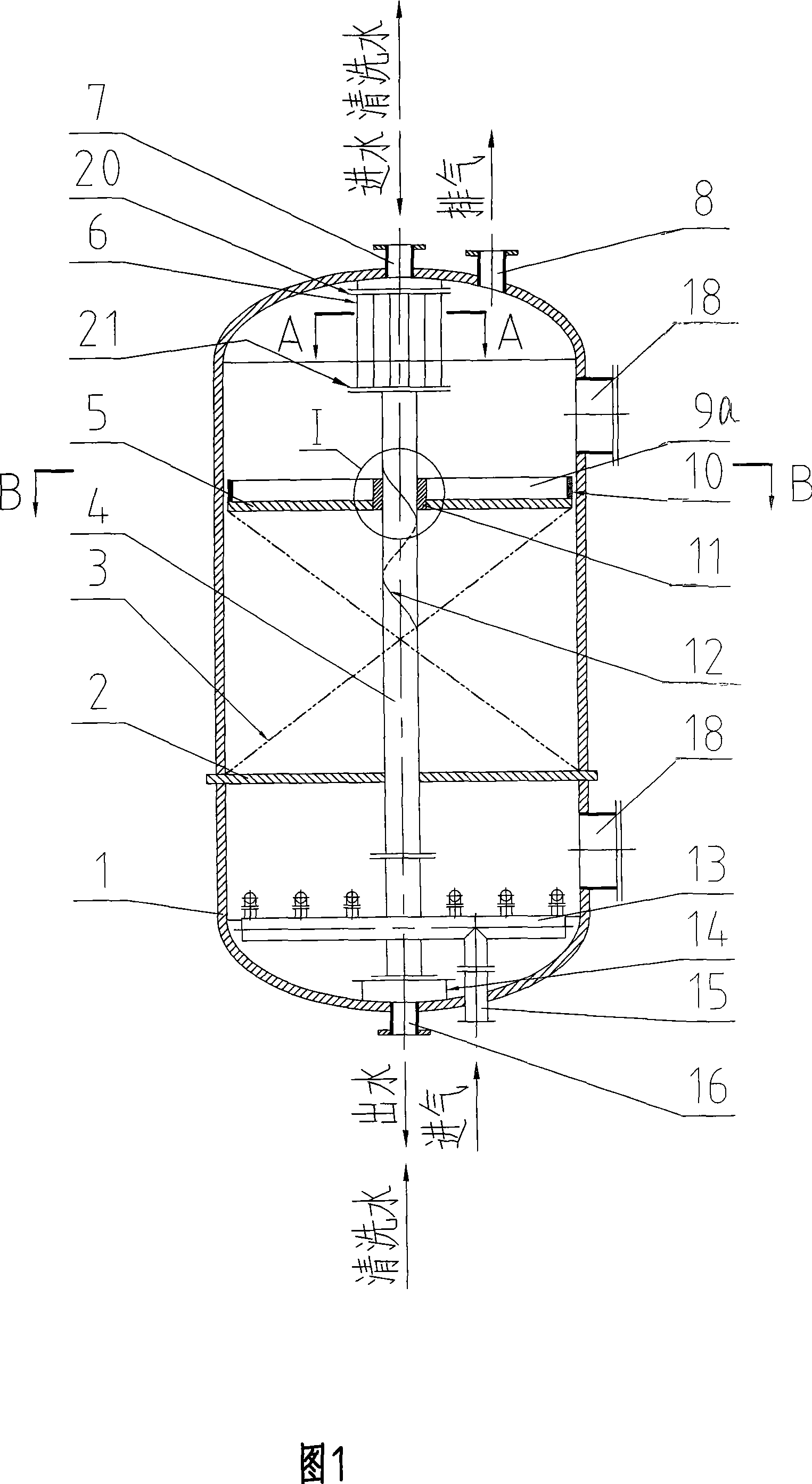
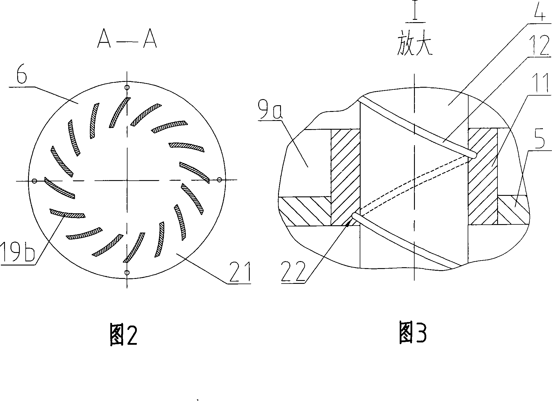
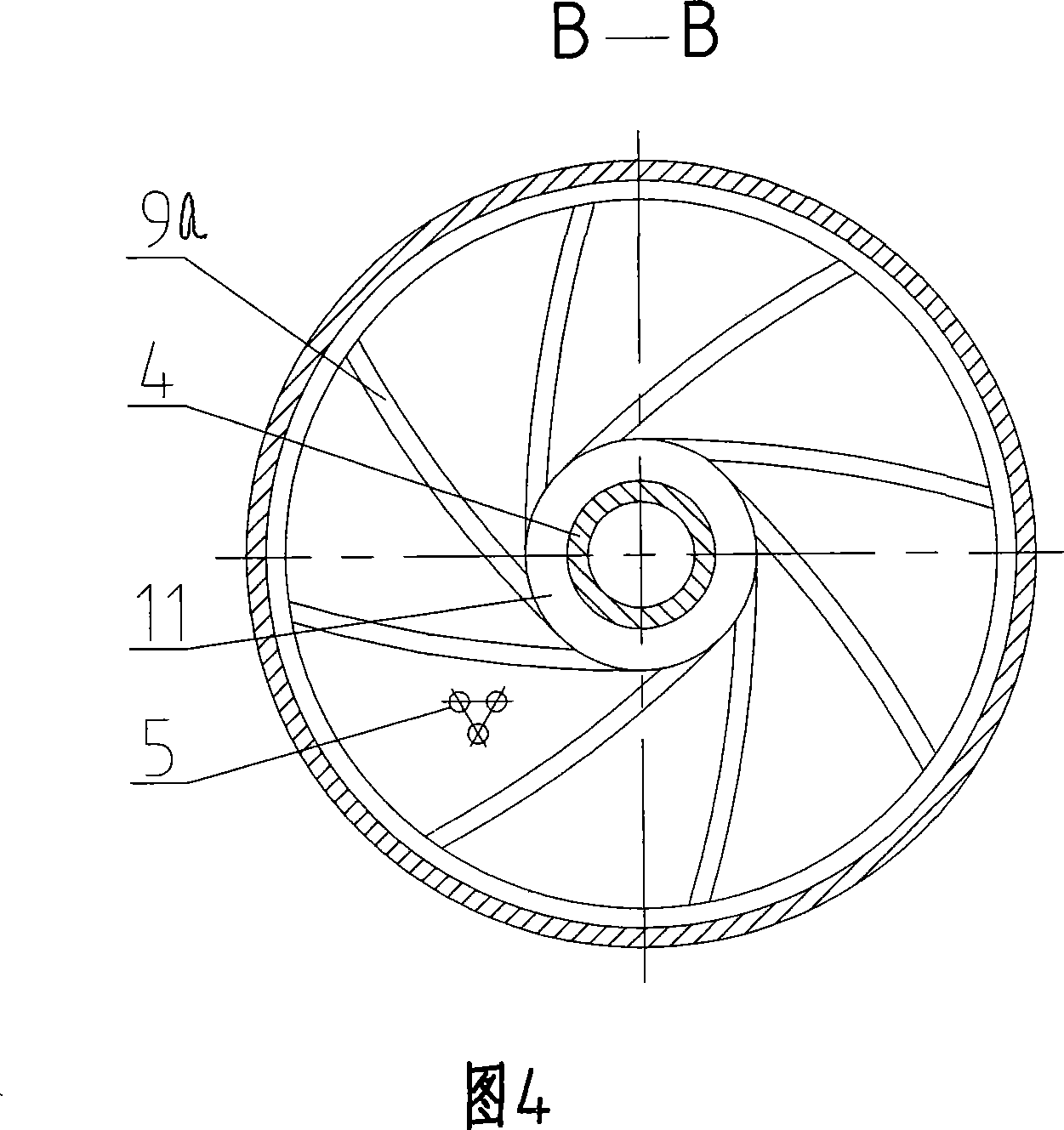
[0015] Embodiment 1: Referring to Figures 1 to 4, the fiber filter element in this embodiment can rotate and displace the filter as a downward flow filter structure. It has a tank body 1, and the tank body 1 is composed of upper and lower heads and a middle tank body after welding. A water inlet 7 and an exhaust port 8 are arranged on the upper head of the tank body 1 , and a water outlet 16 and an air inlet 15 are arranged on the lower head of the tank body 1 . A manhole 18 is provided on the tank body 1 . A water distribution device 6 and a water outlet device 14 communicated with the water inlet 7 and the water outlet 16 are respectively provided. The bottom in the tank body 1 is provided with a gas distribution device 13 communicating with the air inlet 15, the lower end in the tank body 1 is provided with a fixed orifice 2, and the upper end in the tank body 1 is provided with a movable orifice 5. A fiber filter element 3 is arranged between the fixed orifice plate 2 an...

Embodiment 2

[0017] Embodiment 2: Referring to FIG. 5 , the fiber filter element in this embodiment can rotate and displace the filter as an upward flow filter structure. Its basic structure and working principle are the same as those of Embodiment 1, the only difference is that the water outlet 16 (ie: cleaning water inlet) is set on the upper head of the housing 1, and the water inlet 9 (ie: cleaning water outlet) is set On the lower head of the housing 1 , the fixed orifice plate 2 is arranged at the inner upper end of the housing 1 , and the floating orifice plate 6 is arranged at the inner lower end of the housing 1 .

Embodiment 3

[0018] Embodiment 3: Referring to FIG. 6 , the fiber filter element in this embodiment can rotate and displace the filter as a downward flow filter structure. The tank body 1 is composed of two sections of cylindrical tank bodies and a section of conical tank body 17 with a fiber filter element 3 fixedly connected in the middle. The diameter of the conical tank body 17 is from large to small; Make a cone. This structure of the tank body 1 is more conducive to the realization of deep filtration.


PUM


Abstract

The invention relates to a segregating unit, which is a filter with a rotatable fibre strainer, comprising water inlet/ water outlet, air inlet/air outlet and water distribution/water out unit mounted on the tank, air distributing device mounted in the tank, and fibre strainer connected fixedly with the fixed pore plate and moving pore plate and mounted between thereof in the tank. The method is characterized in that: a support guide tube is mounted at the center of the tank and two ends thereof are securely connected with the water distribution/water out unit, a conduit which hitches on the support guide tube and is a helical pair therewith, the moving pore plate which is securely connected with the round plate is securely connected with the conduit, and rotatable fibre strainer composed of plurality of swirl vanes is mounted between the conduit and the round plate. The device has a simple structure, operates and maintains conveniently, and easily realizes large-scale equipment. The device has an advantage of a high filtrating precision, a big area, a large pollution-cutting capability, a long filtrating cycle, a big water-making, a excellent filtrating quality, a and reliable property.

Description

technical field [0001] The invention relates to a separation device, which is a filter with rotatable displacement of fiber filter element for water and aqueous solution. Background technique [0002] The existing fiber filter has a structure in which several fiber bundles are evenly distributed between the fixed orifice plate and the moving orifice plate, and the porosity of the fibers is adjusted by squeezing the moving orifice plate in the axial direction by the natural momentum of water inflow and outflow. The disadvantage is that several fiber bundles of the fiber filter element cannot be compacted or completely stretched and loosened, and the purpose of adjusting the porosity of the fibers and the requirements of high-precision water quality cannot be achieved, and the filtration resistance is large. Contents of the invention [0003] The technical problem to be solved by the present invention is to substantially improve the existing technology and provide a fiber fi...

Claims


Application Information

Patent Timeline
Patent Type & Authority Applications(China)
IPC IPC(8): B01D24/10B01D24/46
Inventor 苑德春崔生荣姚钟伦
Owner NORTHEAST DIANLI UNIVERSITY
Why Eureka
Try Eureka