Tool type steel pipe cutting machine

A cutting machine and tool-type technology, applied in the field of pipe cutting equipment, can solve the problems of poor processing quality, high labor intensity, pollution of the environment, etc., achieve fast cutting speed, improve work efficiency, and avoid the effect of knife-edge eversion

Inactive Publication Date: 2007-10-17
北京城建建设工程有限公司
View PDF0 Cites 5 Cited by
  • Summary
  • Abstract
  • Description
  • Claims
  • Application Information

AI Technical Summary

Problems solved by technology

[0003] The purpose of the present invention is to provide a tool-type steel pipe cutting machine to solve the problems of high labor intensity, low efficiency, poor processing quality and environmental pollution in traditional steel pipe cutting devices

Method used


Image

  • Tool type steel pipe cutting machine
  • Tool type steel pipe cutting machine
  • Tool type steel pipe cutting machine

Examples


Embodiment Construction

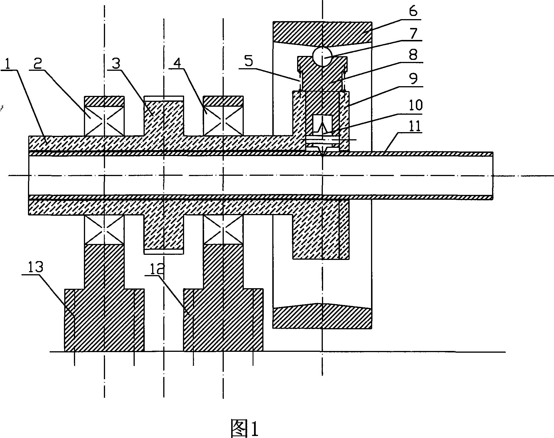
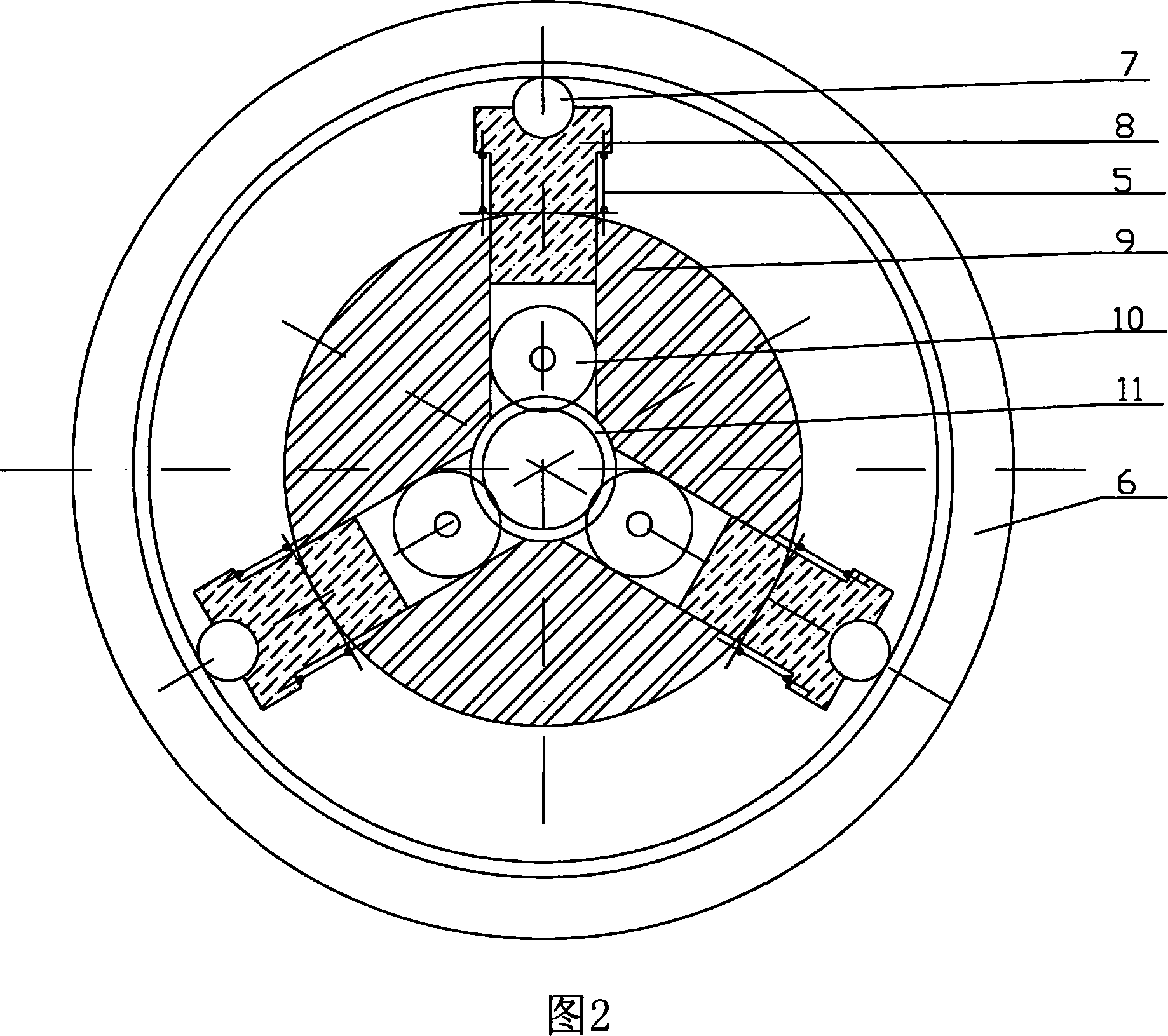
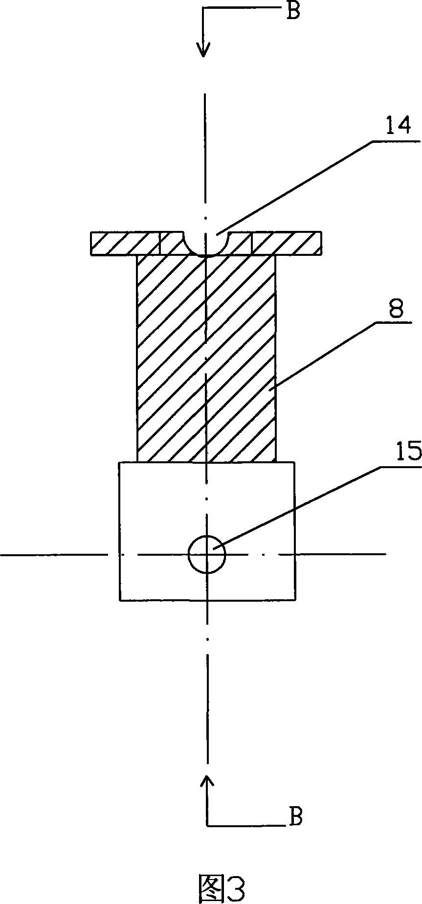
[0018] In Fig. 1, the specific technical solution of the present invention is provided, the knife rest 1 is cylindrical, and the knife rest 1 is fixed on the bearing supports 12, 13 through bearings 2, 4, and a belt pulley is fixed in the middle of the knife rest 1 3. There is a driving motor (not shown in the figure) to drive the knife rest 1 to rotate through a belt. A chuck 9 is fixed on the right end of the tool rest 1, and the axes of the tool rest 1 and the chuck 9 overlap each other, and the chuck 9 is a chuck used on a common lathe. A cutter head 8 is placed in the chute arranged radially at an angle of 120° C. on the chuck 9 . The inner end of the cutter head 8 is fixed with a hob 10 through a groove and a rotating shaft. The outer diameter of the hob 10 is smaller than the width of the chute of the chuck 9 and is located inside it. The outer end of cutter head 8 has a circle of bosses, and a back-moving spring 5 is arranged to be enclosed within the outer part of th...


PUM


Abstract

The invention discloses a tool type steel tube cutter comprising: a mechanical drive device essentially composed of bearings and bearing supports which are fixed on both ends of a barrel-shaped tool post, a driving belt pulley disposed on the middle of the tool post and a drive motor; a tool post part essentially composed of the barrel-shaped tool post, a lathe chuck disposed on one end of the tool post, a movable cutter head positioned within three grooves of the chuck, and a hob disposed in inner end of the chuck and radially fixed via a shaft. A groove for receiving balls is provided in an outer end face of the cutter head, which outer end part has a reset spring. The steel tube is fixed within a central hole of the tool post and the chuck via a fixing fixture on both ends. The invention further includes a cutter feed device with an annular wall in arc structure protruding along axial central part. Three balls arranged on outer end of the three cutter heads contact with the annular wall of the cutter feed device. Compared with traditional tube cutter, the invention has advantages of low use cost, enhanced work efficiency, basically neither noise nor dust pollution.

Description

technical field [0001] The invention relates to a pipe cutting device. Background technique [0002] Traditional steel pipe cutting devices use abrasive wheel saws to complete the cutting work. This cutting device has the following disadvantages: 1. The labor intensity of the operation is high, the cutting speed is slow, and the efficiency is low; 2. The grinding wheel is expensive, easy to damage, and high in use cost; 3. The processed knife edge is not smooth and the quality is not good; 4. The safety of operation is poor; 5. There is noise and dust pollution to the environment. Contents of the invention [0003] The object of the present invention is to provide a tool-type steel pipe cutting machine to solve the problems of high labor intensity, low efficiency, poor processing quality and environmental pollution existing in traditional steel pipe cutting devices. [0004] The tool-type steel pipe cutting machine of the present invention has a technical solution for ac...

Claims


Application Information

Patent Timeline
Patent Type & Authority Applications(China)
IPC IPC(8): B23D21/04B23D36/00B23D35/00
Inventor 侯荣德
Owner 北京城建建设工程有限公司
Why Eureka
Try Eureka