Cooling device, heating device and communication device

A technology of refrigeration equipment and communication equipment, applied in the fields of refrigeration equipment, heating equipment and communication equipment, can solve the problems of high TEC operation cost and large heat fluctuation of TEC air-conditioning cabinets/boxes, so as to improve refrigeration efficiency and buffer energy impact , the effect of maintaining a constant local temperature

Inactive Publication Date: 2007-10-17
HUAWEI TECH CO LTD
View PDF0 Cites 11 Cited by
  • Summary
  • Abstract
  • Description
  • Claims
  • Application Information

AI Technical Summary

Problems solved by technology

[0007] Finally, when the external ambient temperature changes drastically, a large amount of heat will be transferred to the cabinet / box, which will cause the heat in the TEC air-conditioning cabinet / box to fluctuate greatly, and the continuous impact of external heat will cause the TEC to start and stop repeatedly , which makes the TEC work repeatedly for a long time, which leads to higher operating costs of the TEC

Method used


Image

  • Cooling device, heating device and communication device
  • Cooling device, heating device and communication device
  • Cooling device, heating device and communication device

Examples


Embodiment 1

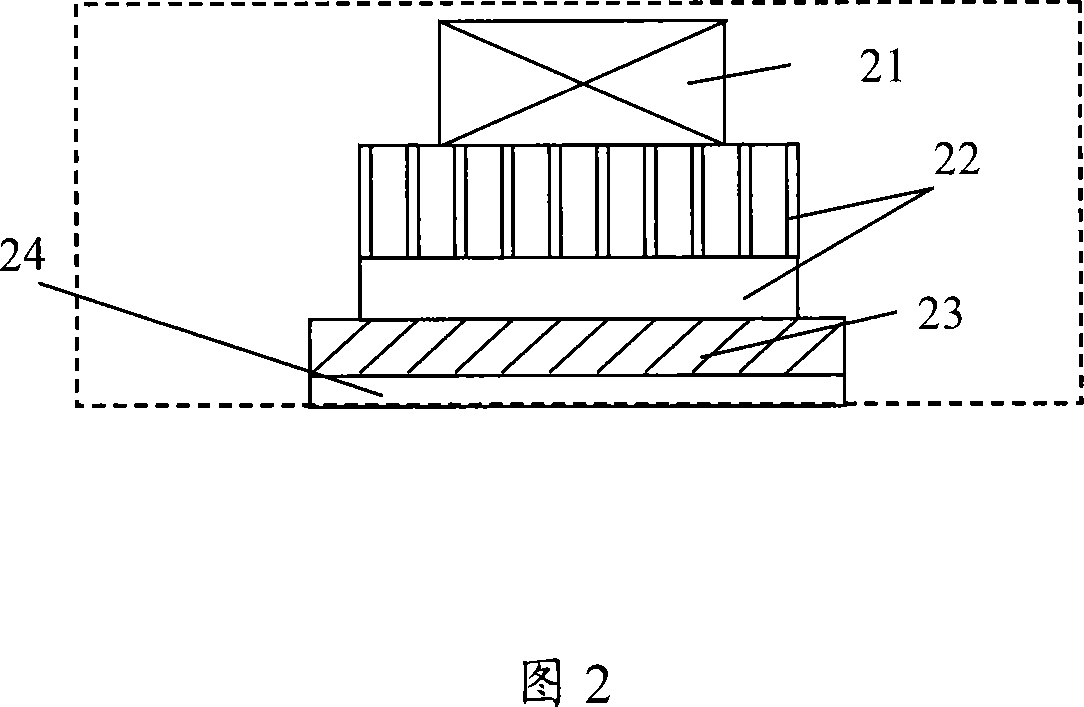
[0028] Referring to Figure 2, Figure 2 is a schematic diagram of the first embodiment of the refrigeration device of the present invention. It can be seen from Figure 2 that the device includes a cold end radiator 22 and a cold end phase change unit 23. The cold end phase change unit 23 is assembled in the The cold-end radiator 22 is used for releasing cooling capacity, and the cold-end phase change unit 23 is filled with a phase change material for accumulating cooling capacity.

[0029] The cooling capacity in the electronic device 24 is transmitted to the cold-end phase change unit 23. One side of the cold-end phase change unit 23 is connected to the electronic device 24 (such as a semiconductor chip) through a thermal grease or a thermal pad, and the other side is connected to The base plates of the cold-end radiator 22 are connected, and the cold-end fan 21 distributes the cooling capacity to the cold-end space, so that the cold-end space can be cooled. In order to enable the...

Embodiment 2

[0035] In the embodiment of the refrigeration device of the present invention, the cold-end phase change unit is built into the cold-end radiator. For example, one side of the cold-end phase change unit is connected to the base plate of the cold-end radiator, and the other side is connected to the fin of the cold-end radiator. Connected.

Embodiment 3

[0037] The embodiment of the refrigeration device of the present invention adds a cold-end phase change unit on the side of the fin of the cold-end radiator.

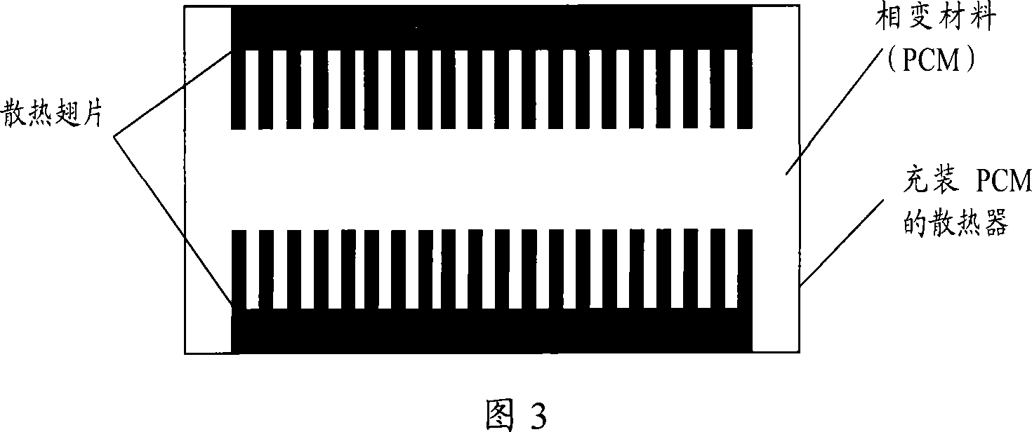
[0038]At the same time, the cold end phase change unit or the hot end phase change unit built-in heat dissipation fins or heat pipes can uniform the temperature of the PCM phase change material, so that its heat storage performance can be fully exerted. The temperature of the PCM material is uniformed by the method of built-in heat dissipation fins, as shown in Fig. 3. At the same time, the upper part of the heat sink filled with PCM material can also have external fins. The method of using built-in heat pipe to homogenize the temperature of the PCM material can be seen in Fig. 4. At the same time, the upper part of the radiator filled with PCM material can also have external fins.

[0039] Heating device embodiment one

[0040] The embodiment of the present invention also provides a heating device. Referring to FIG. 5, FIG...


PUM


Abstract

The invention discloses a refrigerating installation, heating equipment and communication device belonging to electronic communication technical field. The installation comprises cold junction radiator which is used for releasing refrigerating duty and cold junction phase transition unit which is set at the cold junction radiator and filled with the phase transition for gathering refrigerating duty, and the fins or the heat pipe are arranged in the cold junction radiator. The invention amortizes the local low temperature produced by refrigeration and makes not produce condensation water in the cabinet or amortizes the local high temperature produced by heating process and further improve the refrigerating or heating efficiency. Additionally, the invention can effectively decrease the numbers of start/stop and operation period to reduce operation cost.

Description

Technical field [0001] The present invention relates to the field of electronic communication technology, in particular to refrigeration devices, heating devices and communication equipment. Background technique [0002] Thermoelectric cooler (TEC, Thermoelectric Cooler) technology is usually used in communication cabinet equipment with low power consumption and high reliability requirements. In the following, a thermoelectric refrigerator in the prior art will be introduced with reference to FIG. 1. [0003] As can be seen from FIG. 1, the TEC includes a cold-end fan 11, a cold-end radiator 12, a cold-end space 13, a semiconductor chip 14, a hot-end space 15, a heat-insulating sealing layer 16, a hot-end radiator 17, and a hot-end fan 18. Among them, the cold-end fan 11, the cold-end radiator 12, and the cold-end space 13 are arranged on one side of the semiconductor chip 14, and the hot-end space 15, the hot-end radiator 17, and the hot-end fan 18 are on the other side of the s...

Claims


Application Information

Patent Timeline
Patent Type & Authority Applications(China)
IPC IPC(8): H05K7/20F25B21/00F25B21/02
CPCY02B30/66Y02B30/00
Inventor 洪宇平黄文雄
Owner HUAWEI TECH CO LTD
Why Eureka
Try Eureka